Cost Model - Die Casting
You can use the Die Casting cost model to calculate the process times and costs for the die casting manufacturing process in metalworking. In FACTON, there are value rule tables, and at the cost model there are formulas defined that offer you information on:
- The anticipated cycle time,
- the possible process output per time and cycle,
- the material consumption,
- the clamping force and the machine shot mass and
- primary and secondary processing times.
In the cost model Die Casting, a distinction is made between hot and cold chamber processes.
The table shows typical application scenarios of the cost model for parts and industries:
| Typical Parts | Typical Industries |
|---|---|
|
|
You need knowledge of the Die Casting manufacturing process in order to use the cost model.
Procedure
The following example illustrates the process and structure of the Die Casting cost model.
The black triangle helps you identify values that you can enter ![]() .
.
The Consistency Rule Violation check is available to you when entering values. The consistency rule violations check notifies you of missing values and verifies the accuracy of the values entered.
When you hover over one of the Consistency rule violations icons with your mouse, a tooltip appears with the specific reason for the consistency rule violations.
Step 1: Create Should Cost Calculation
Create
- You are logged in as Calculator.
- You are in the Calculations workspace.
- In the ribbon, click on Manage.
- Select the
 Should Cost Calculation
The created calculation opens in a new tab.
You are the owner of the calculation that was created.
- Define the following properties for the Should Cost Calculation in the Details view:
- Material Overhead Rate
- Manufacturing Overhead Rate
- Administrative Overhead Rate
- Sales Overhead Rate
- Development Overhead Rate
- Logistics Overhead Rate
| Reference Company* | |
| Industrial Sector |
|
| Production Location | World » Europe » Germany |
| Reference Company Revenue | 100m EUR |
| Reference Company Material Share | 50% |
| Reference Company Degree of Automation | Medium |
| Production Planning | |
| Production Quantity | 100,000 pc / a |
| Target Profit Rates | |
| Target Profit Rate on Raw Material | 2 % |
| Target Profit Rate on Purchased Material | 2 % |
| Target Profit Rate on Manufacturing | 2 % |
|
* Values are determined for the following properties using value rules based on your inputs under reference companies: |
|
Step 2: Insert Process
Insert Process
- In the Structure view, select the calculation element you wish to insert under the process.
- Click Edit ► Insert ►
 Process in the ribbon.
A process is inserted in the calculation structure.
- Change the label to
- Define the following properties for the process in the Details view:
- In the Details ► General ► Valuation view, select the valuation Cost Model:
A new Cost Model group appears with subgroups.
| Technical Descriptions | |
| Material Classification* |
|
| Manufacturing Method* |
|
| * FACTON recommends the appropriate materials and machines in the queries for the processes by allowing you to select the material classification and manufacturing process. | |
When changing valuations the sub-elements are greyed-out and no longer considered in the calculation.
For more information on the Die Casting cost model, see: Properties of the Cost Model - Die Casting
Step 3: Insert Material
Values must be entered at the material for the Density and the Material Classification properties in order to calculate the primary processing times.
Values are determined for the following properties using value rules by selecting the material classification:
- Specific Die Casting Pressure
- Thermal Conductivity
- Specific Heat Capacity
You can view the properties under Details ► General ► Cost Model ► Material.
You can insert
The latter is shown in the following, because it illustrates the inputs required for calculation.
Insert Local Material
- Select the »Die Casting« process in the Structure view.
- Click on Edit ► Insert ►
 Insert New Local Material (Mass).
A local material is inserted under the »Die Casting« process.
- Change the label to »Die Casting Material«.
- In the Details ► Technical Description view, enter a value for the Density (e.g. 2.7 g/cm³).
- Under Details ► Technical Description ► Material Classification, select a material classification.Note
You can use the following material classifications with the cost model:
- Aluminum
- Zinc
- Tin
- Magnesium Alloy
The Material Classification Properties group appears under Technical Description.
- Define the following property in the Details view:
General Price per Unit  1.75 EUR / kg
Values are determined at the process in the Cost Model ► Material group for the following properties using value rules based on the material classification:
- Specific Die Casting Pressure
- Thermal Conductivity
- Specific Heat Capacity
Step 4: Describe Part
The part properties are required to determine the cycle time.
Describe Part
- In the Structure view, select the process
- Enter the following values for the part in the Details ► Cost Model ► Part view.
These values are required in order to calculate additional values:
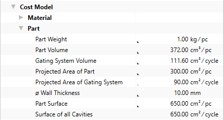
Additional values are calculated based on the input values for the part and shown at the process
| Part Property | Group | Calculated Value |
|---|---|---|
| Gating System Volume | Material |
|
| Part Volume | Part | Part Weight |
| Projected Area of Part | Projected Area of Gating System | |
| Projected Area of Part | Clamping Force |
|
| Wall Thickness | Primary Processing Times |
|
Step 5: Insert Machine
You can use the calculated Required Total Clamping Force and the Material Usage Weight to determine and insert the required machine. The required total clamping force is the minimum amount of force a machine must supply in order to manufacture the described part.
To calculate the number of cavities, values must be entered at the machine for the Machine Type, Available Clamping Force and Machine Shot Mass properties.
You can insert
The latter is shown in the following, because it illustrates the inputs required for calculation.
Insert Local Machine
- Select the »Die Casting« process in the Structure view.
- Click on Edit ► Insert ►
 Insert New Local Machine in the ribbon.
A machine is inserted under the »Die Casting« process.
- Change the label to »Die Casting Machine«.
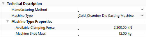
- Under Details ► Technical Description ► Machine Type select a machine type for the »Die Casting Machine«.Note
You can use the following machine types with the cost model:
- Cold-Chamber Die Casting Machine
- Hot-Chamber Die Casting Machine
The Machine Type Properties group appears under Technical Description.
- In the Details ► Technical Description view, enter a value for the following properties:
- Available Clamping Force
- Machine Shot Mass
- Define the following properties for the machine in the Details view:
Acquisition Costs Acquisition Value 200,000 EURFixed Machine Costs Depreciation Period 6 a
Sufficient clamping force for the machine is determined by the sum of the Required Clamping Force for Part and Clamping Force by Projected Area of Gating System.
Calculated values of the Die Casting cost model:
The following values are calculated using the data entered and then shown in the Details ► General ► Cost Model view:
- Cycle Time
- Ʃ Measure Values Cycle Time
- Cycles per Time
- Output per Cycle
- Output per Time
- Time per Unit Output
- Manufacturing Scrap Rate
- Production Cost
Step 6: Insert Worker and Tool
Insert Worker
- In the Structure view, select the
- In the ribbon, click on Edit ► Insert ►
 Worker.
The corresponding labor costs for the worker are determined based on the sector, the reference location, the reference date and the labor group.
Insert Tool
- In the Structure view, select the process
- Click Edit ► Insert ►
 Insert New Local Tool.
The tool is inserted under the process.
Step 7: Additional Fine Tuning
You can continue fine tuning the settings in the Details ► General ► Cost Model view:
| Group | Properties |
|---|---|
| Material |
|
| Clamping Force |
|
| Secondary Processing Times |
|
| Primary Processing Times |
|
Properties of the Cost Model - Die Casting
Material Group
The material properties used to calculate the cost model are shown in this group.
| Material Properties | Description | Input Possible |
Calculated |
Required |
|---|---|---|---|---|
| Density |
Density of the material This value is required and can be managed at the material (Details View ► Technical Description), or is applied when global templates are inserted. |
x | ||
| Specific Die Casting Pressure |
Specific die casting pressure required per area for a given material
|
with F12 | ||
| Thermal Conductivity |
Thermal conductivity of the material
|
with F12 | ||
| Specific Heat Capacity |
Specific heat capacity of the material
|
with F12 | ||
| % Additional Value for Material Loss | Percentaged additional value on Material Usage Weight for Material Loss which gets lost during the process and cannot be recycled. | direct | ||
| Material Usage Weight |
Required material weight incl. gating system weight is calculated from:
|
x | ||
| Material Usage Volume |
Required material volume incl. gating system volume
|
x | ||
| Recyclable Material |
Material mass of the gating system which can be recycled
|
x | ||
| Material Loss |
Process-related and non-recyclable material loss
|
x |
Part Group
The part properties used to calculate the cost model are shown in this group.
| Part Properties | Description | Input Possible |
Calculated |
Required |
|---|---|---|---|---|
| Part Weight | Weight of the part Is calculated when entering a value for the part volume |
direct | ||
| Part Volume | Volume of the part Is calculated when entering a value for the part weight |
direct | x | |
| Gating System Volume | Volume of the gating system | direct | x | |
| Projected Area of Part | The area of the part projected in the mold parting surface | direct | x | |
| Projected Area of Gating System | The area of the gating system projected in the mold parting surface Is calculated when entering a value for the projected area of the part is calculated from:
|
with F12 | ||
| Wall Thickness | Average wall thickness of the part | direct | x | |
| Part Surface | Surface of the part | direct | x | |
| Surface of all Cavities | Surface of all cavities in the tool | direct |
Clamping Force Group
The clamping force properties used to calculate the cost model are shown in this group.
| Clamping Force Properties | Description | Input Possible |
Calculated |
Required |
|---|---|---|---|---|
| Clamping Force by Projected Area of Part | Clamping force by projected area of part in the mold parting surface is calculated from:
|
x | ||
| % Additional Clamping Force for Safety | Percentaged additional clamping force for safety ratio by projected area Is calculated when entering a value for the additional clamping force for safety |
direct | ||
| Additional Clamping Force for Safety | Absolute additional clamping force for safety ratio by projected area Is calculated when entering a value for the % additional clamping force for safety |
direct | ||
| % Additional Clamping Force for Sliders | Percentaged additional clamping force for sliders by projected area Is calculated when entering a value for the additional clamping force for sliders |
direct | ||
| Additional Clamping Force for Sliders Ratio | Absolute additional clamping force for sliders by projected area Is calculated when entering a value for the additional clamping force for sliders |
direct | ||
| Required Clamping Force for Part |
Required clamping force for the part with additional clamping forces
|
x | ||
| Clamping Force by Projected Area of Gating System |
Clamping force by projected area of the gating system in the mold parting surface
|
x | ||
| Required Total Clamping Force |
Required total clamping force for all cavities and the gating system
|
x |
Machine Group
The machine properties used to calculate the cost model are shown in this group.
| Machine Properties | Description | Input Possible |
Calculated |
Required |
|---|---|---|---|---|
| Clamping Force of the Machine |
Maximum clamping force of the machine that is available This value is required and can be managed at the machine (Details View ► Technical Description ► Machine Type Properties), or is applied when global templates are inserted. |
x | ||
| Machine Shot Mass |
Maximum shot mass of the machine that is available This value is required and can be managed at the machine (Details View ► Technical Description ► Machine Type Properties), or is applied when global templates are inserted. |
x | ||
| Hot Chamber | Displays the hot chamber method | |||
| Possible Cavity Count by Clamping Force |
The possible count of cavities determined with respect to the available clamping force
|
x | ||
| Possible Cavity Count by Shot Mass |
The possible count of cavities determined with respect to the available shot mass
|
x | ||
| Cavity Count | Number of cavities is calculated from:
|
with F12 |
Secondary Processing Times Group
The secondary processing times used to calculate the cost model are shown in this group.
| Secondary Processing Times | Description | Input Possible |
Calculated |
Required |
|---|---|---|---|---|
| Insert and Demolding Time | Time for inserting and demolding the part | direct | ||
| Sliders Count | Number of sliders of the tool | direct | ||
| Greasing Time | Time for greasing all cavities of the tool Depends on:
|
with F12 | ||
| Additional Secondary Processing Times | Chance to add secondary processing times that have not been considered yet | direct | ||
| Secondary Processing Time | Necessary idle times of a process in which the actual activity of a process are not performed is calculated from:
|
x |
Primary Processing Times Group
The primary processing times used to calculate the cost model are shown in this group.
| Primary Processing Times | Description | Input Possible |
Calculated |
Required |
|---|---|---|---|---|
| Cooling Time | Time for cooling down the part for removal and further usage is calculated from:
|
x | ||
| Tool Open Close Time |
Time for opening and closing the tool
|
with F12 | ||
| Ladle Time | Time to ladle the material Depends on:
|
with F12 | ||
| Fill Time |
Time to fill the tool
|
with F12 | ||
| Additional Primary Processing Times | Chance to add primary processing times that have not been considered yet | direct | ||
| Primary Processing Time |
Time in which the actual activity of a process is performed
|
x |