Cost Model - Circuit Board Assembling
Circuit board assembling is a manufacturing process comprising multiple individual processes that are linked serially. The machine with the longest cycle time determines the cycle time for the entire process chain.
The following individual processes must be performed:
- Printing the PCB Panel
- Assembling the PCB Panel
- Soldering
- Depanelization
- Visual Inspection
- PCB Inspection
You can use the Circuit Board Assembling cost model to calculate the process times and costs for the circuit board assembling manufacturing process in metal working. In FACTON, there are value rule tables, and at the cost model there are formulas defined that provide you with information on:
- the anticipated cycle time for the entire process chain and individual processes,
- the possible process output per time and cycle,
- the material consumption,
- the printing, soldering, cutting and scanning speeds and
- the primary and secondary processing times.
You need knowledge of the Circuit Board Assembling manufacturing process in order to use the cost model.
Procedure
The following example illustrates the process and structure of the Circuit Board Assembling cost model.
The black triangle helps you identify values that you can enter ![]() .
.
The Consistency Rule Violation check is available to you when entering values. The consistency rule violations check notifies you of missing values and verifies the accuracy of the values entered.
When you hover over one of the Consistency rule violations icons with your mouse, a tooltip appears with the specific reason for the consistency rule violations.
Step 1: Create Should Cost Calculation
Create
- You are logged in as Calculator.
- You are in the Calculations workspace.
- In the ribbon, click on Manage.
- Select the
 Should Cost Calculation
The created calculation opens in a new tab.
You are the owner of the calculation that was created.
- Define the following properties for the Should Cost Calculation in the Details view:
- Material Overhead Rate
- Manufacturing Overhead Rate
- Administrative Overhead Rate
- Sales Overhead Rate
- Development Overhead Rate
- Logistics Overhead Rate
| Reference Company* | |
| Industrial Sector |
|
| Production Location | World » Europe » Germany |
| Reference Company Revenue | 100m EUR |
| Reference Company Material Share | 50% |
| Reference Company Degree of Automation | Medium |
| Production Planning | |
| Production Quantity | 100,000 pc / a |
| Target Profit Rates | |
| Target Profit Rate on Raw Material | 2 % |
| Target Profit Rate on Purchased Material | 2 % |
| Target Profit Rate on Manufacturing | 2 % |
|
* Values are determined for the following properties using value rules based on your inputs under reference companies: |
|
Step 2: Insert Process for Process Chain
For circuit board assembling, you need a calculation structure that visualizes the process chain. Set the valuation for the Circuit Board Assembling cost model at this process. This displays the properties for the process chain.
The separate Cycle Times for the individual processes are displayed at the »Circuit Board Assembling« process in the Details ► Cost Model view along the entire process chain. The cycle time for the process chain is determined based on the process with the longest cylce time for the machine.
Insert Process
- In the Structure view, select the calculation element you wish to insert under the process.
- Click Edit ► Insert ►
 Process in the ribbon.
A process is inserted in the calculation structure.
- Change the label to
- Define the following properties for the process in the Details view:
- In the Details ► General ► Valuation view, select the valuation Cost Model:
A new Cost Model group appears with subgroups.
| Technical Descriptions | |
| Material Classification* |
|
| Manufacturing Method* | |
| * FACTON recommends the appropriate materials and machines in the queries for the processes by allowing you to select the material classification and manufacturing process. | |
When changing valuations the sub-elements are greyed-out and no longer considered in the calculation.
For more information on the Circuit Board Assembling cost model, see: Properties of the Cost Model - Circuit Board Assembling
Step 3: Describe Part
The part properties are required in order to determine the cycle time.
For a mixed or double-sided assembly, note that the process chain repeats itself, and thus increases the cycle time.
Describe Part
- In the Structure view, select the process
- Enter the following values for the part in the Details ► Cost Model ► Part view.
These values are required in order to calculate additional values:
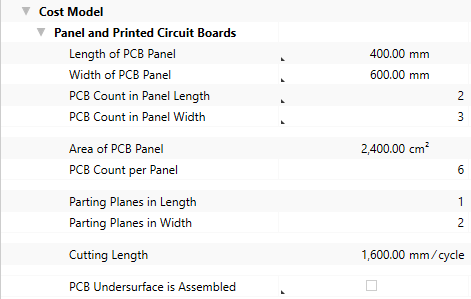
Additional values are calculated based on the input values for the part and shown at the process
| Part Property | Group | Calculated Value |
|---|---|---|
| Length of PCB Panel | PCBs and Circuit Boards | Area of PCB Panel |
| Width of PCB Panel | ||
| PCB Count in Panel Length | PCBs and Circuit Boards |
|
| PCB Count in Panel Width |
Step 4: Insert Material
Values must be entered at the material for the Material Type, Gross Quantity, Material Classification, PCB Placement Method and the PCB Placement Complexity properties in order to calculate the necessary press force.
The PCB placement method and the PCB placement complexity are relevant for determining the cycle time. Select the PCB placement method and the PCB placement complexity at the material with the material classification Parts » Electronic Parts.
PCB Placement Method
This cost model allows you to choose between the Collect & Place (C&P) and Pick & Place (P&P) cost models.
PCB Placement Complexity
By entering the PCB placement complexity (in percent), you can define how complex the placement of the electronic component is related to the definition in IPC 9850.
You can insert
The latter is shown in the following, because it illustrates the inputs required for calculation.
Insert Local Material
- Select the »Circuit Board Assembling« process in the Structure view.
- Click on Edit ► Insert ►
 Insert New Local Material (Pieces) in the ribbon.
A local material is inserted under the »Circuit Board Assembling« process.
- Change the label to »Ceramic Capacitor 10uF/ X7R«.
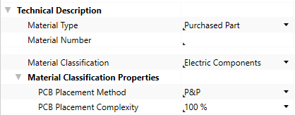
- Define the following properties in the Details view:
General Material Type Purchased Part Gross Quantity 120 pcs / cycle Technical Description Material Classification Electronic Components NoteYou can use the following material classifications with the cost model:
- Electronic Components
The Material Classification Properties group appears under Technical Description.
- In the Details ► Technical Description view, enter a value for the following properties:
- PCB Placement Method
- PCB Placement Complexity
Entering the PCB Placement Method and the Placement Capacity calculates the following value:
- Cost Model ► Process Chain ► Placement group: Weighted Quantity P&P (depending on selected placement method)
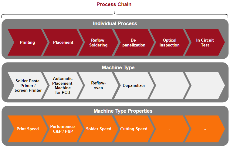
Step 5: Build Process Chain - Insert Machine
In order to visualize the individual processes of the process chain, insert all of the required machines under the »Circuit Board Assembling« process. Each individual process contains a certain machine type and a manufacturing process with specific process properties. The diagram shows the process chain with all individual manufacturing processes and their machine properties:
You can insert
The latter is shown in the following, because it illustrates the inputs required for calculation.
Individual Process - Printing
In order to calculate the Printing cycle time, the Machine Type and Print Speed properties must be entered at the machine.
When inserting multiple machines for printing, the Minimum Print Speed is used to calculate the cycle time.
Insert Machine for Printing
- Select the »Circuit Board Assembling« process in the Structure view.
- Click Edit ► Insert ►
 Insert New Local Machine in the ribbon.
A machine is inserted under the »Circuit Board Assembling« process.
- Change the label to »Screen Printing Machine«.
- Under Details ► Technical Description ► Machine Type select a machine type for the »Screen Printing Machine«.Note
You can use the following machine type with the cost model:
- Solder Paste Printer / Screen Printer
The Machine Type Properties group appears under Technical Description.
- In the Details ► Technical Description view, enter a value for the following properties:
- Print Speed
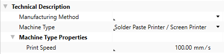
- Print Speed
Entering the machine property Print Speed and the length of the PCB panel calculates the following values:
- Cost Model ► Process Chain ► Printing group:
- Print Time
- Printing Cycle Time
Individual Process - Placement
To calculate the placement cycle time, the Machine Type and Performance for C&P or P&P properties must be entered at the machine.
Insert Machine for Placement
- Select the »Circuit Board Assembling« process in the Structure view.
- Click Edit ► Insert ► Insert New Local Machine in the ribbon.
A machine is inserted under the »Circuit Board Assembling« process.
- Change the label to »Placement Machine«.
- Under Details ► Technical Description ► Machine Type select a machine type for the »Placement Machine«.Note
You can use the following machine type with the cost model:
- Automatic Placement Machine for PCB
The Machine Type Properties group appears under Technical Description.
- In the Details ► Technical Description view, enter a value for the following properties:
- Performance C&P or Performance P&P
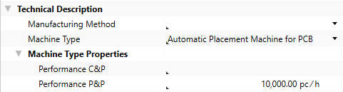
- Performance C&P or Performance P&P
Entering the machine property Performance calculates the following values:
- Cost Model ► Process Chain ► Placement group:
- Weighted Quantity P&P
- Placement Time P&P
- Placement Cycle Time
Individual Process - Soldering
To calculate the soldering cycle time, the Machine Type and Solder Speed properties must be entered at the machine.
If you insert multiple machines for printing, the Minimum Solder Speed is used to calculate the cycle time.
Insert Machine for Soldering
- Select the »Circuit Board Assembling« process in the Structure view.
- Click Edit ► Insert ► Insert New Local Machine in the ribbon.
A machine is inserted under the »Circuit Board Assembling« process.
- Change the label to »Reflow Oven«.
- Under Details ► Technical Description ► Machine Type select a machine type for the »Reflow Oven«.Note
You can use the following machine type with the cost model:
- Reflow Oven
The Machine Type Properties group appears under Technical Description.
- In the Details ► Technical Description view, enter a value for the following properties:
- Solder Speed
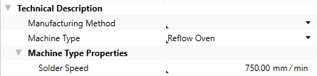
- Solder Speed
Entering the machine property Solder Speed calculates the following values:
- Cost Model ► Process Chain ► Soldering group:
- Solder Time
- Reflow Soldering Cycle Time
Individual Process - Depanelization
To calculate the Depanelization cycle time, the Machine Type and Cutting Speed properties must be entered at the machine.
Insert Machine for Depanelization
- Select the »Circuit Board Assembling« process in the Structure view.
- Click Edit ► Insert ► Insert New Local Machine in the ribbon.
A machine is inserted under the »Circuit Board Assembling« process.
- Change the label to »Depanelizer«.
- Under Details ► Technical Description ► Machine Type, select a machine type for the »Depanelizer«.Note
You can use the following machine types with the cost model:
- Depanelizer
The Machine Type Properties group appears under Technical Description.
- In the Details ► Technical Description view, enter a value for the following properties:
- Cutting Speed
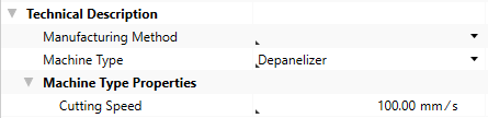
- Cutting Speed
Entering the machine property Cutting Speed calculates the following values:
- Cost Model ► Process Chain ► Depanelization group:
- Print Speed and
- Depanelization Cycle Time
Individual Process - Visual Inspection
To calculate the visual inspection cycle time, you must enter a value for the Scan Speed at the »Circuit Board Assembling« process.
Enter scan speed for visual inspection
- Select the »Circuit Board Assembling« process in the Structure view.
- Under Details ► General ► Cost Model ► Process Chain ► Visual Inspection, enter a value for the Scan Speed property (e.g. 100 cm²/s).
Entering the property Scan Speed and area of the PCB panel calculates the following value:
- Cost Model ► Process Chain ► Visual Inspection group:
- Visual Inspection Cycle Time
Single Process - PCB Inspection
To calculate the cycle time you must enter a value for the Test Time at the »Circuit Board Assembling« process.
Insert test time for PCB inspection
- Select the process »Circuit Board Assembling«.
- Under Details ► General ► Cost Model ► Process Chain ► PCB Inspection, enter a value for the Test Time property (e.g. 2 s / cycle).
Entering the property Test Time calculates the following values:
- Cost Model ► Process Chain ► PCB Inspection group:
- Circuit Test Cycle Time
The process chain cycle time is determined by the longest individual process in the process chain (highest cycle time).
Calculated values of the Circuit Board Assembling cost model:
The following values are calculated using the data entered and then shown in the Details ► General ► Cost Model view:
- Cycle Time
- Ʃ Measure Values Cycle Time
- Cycles per Time
- Output per Cycle
- Output per Time
- Time per Unit Output
- Manufacturing Scrap Rate
- Production Cost
Step 6: Insert Worker and Tool
Insert Worker
- In the Structure view, select the
- In the ribbon, click on Edit ► Insert ►
 Worker.
The corresponding labor costs for the worker are determined based on the sector, the reference location, the reference date and the labor group.
Insert Tool
- In the Structure view, select the process
- Click Edit ► Insert ►
 Insert New Local Tool.
The tool is inserted under the process.
Step 7: Additional Fine Tuning
You can continue fine tuning the following settings:
| Group | Properties |
|---|---|
| PCBs and Circuit Boards | Double-sided Printing |
| Printing |
|
| Placement |
|
| Soldering |
|
| Visual Inspection |
|
| PCB Inspection |
|
Properties of the Cost Model - Circuit Board Assembling
PCBs and Circuit Boards group
The PCB and circuit board properties used to calculate the cost model are shown in this group.
| PCB and Circuit Board Properties | Description | Input Possible |
Calculated |
Required |
|---|---|---|---|---|
| Length of PCB Panel | The length of the PCB panel in production length | direct | x | |
| Width of PCB Panel | The width of the PCB panel | direct | x | |
| PCB Count in Panel Length | The count of PCB in the length of panel | direct | x | |
| PCB Count in Panel Width | The count of PCB in the width of panel | direct | x | |
| Area of PCB Panel | The area of the PCB panel is calculated from:
|
x | ||
| PCB Count per Panel | The total count of PCB per panel is calculated from:
|
x | ||
| Parting Planes in Length | The count of parting planes in direction of production is calculated from:
|
x | ||
| Parting Planes in Width | The count of parting planes in the panel width is calculated from:
|
x | ||
| Cutting Length | Length of the cutting area of all PCBs of the PCB panel is calculated from:
|
x | ||
| Double-sided Printing | Selection whether or not the panel should be printed on both sides | x |
Process Chain ► Printing Group
| PCB and Circuit Board Properties | Description | Input Possible |
Calculated |
Required |
|---|---|---|---|---|
| Loading and Unloading Time | Time for loading and unloading of the machine with the PCB panel | direct | ||
| Print Speed | The operating speed of the machine | with F12 | x | |
| Print Time | The time it takes to print the PCB panel is calculated from:
|
x | ||
| Count of Printers | Count of machines used in the process | |||
| Printing Cycle Time | Total time of the printing operation is calculated from:
|
x |
Process Chain ► Placement Group
| PCB and Circuit Board Properties | Description | Input Possible |
Calculated |
Required |
|---|---|---|---|---|
| Loading and Unloading Time | Time for loading and unloading of the machine with the PCB panel | direct | ||
| Performance C&P | Max count of electronic components per time to be assembled with Collect & Place | with F12 | x | |
| Performance P&P | Max. count of electronic components per time to be assembled with Pick & Place | with F12 | x | |
| Weighted Quantity P&P | With placement complexity weighted quantity of electronic components to be assembled with Collect & Place | x | ||
| Weighted Quantity P&P | With placement complexity weighted quantity of electronic components to be assembled with Pick & Place | x | ||
| Placement Time C&P | Time for assembling of the PCB panel with Collect & Place | x | ||
| Placement Time P&P | Time for assembling of the PCB panel with Pick & Place | x | ||
| Placement Cycle Time | Total time of the placement operation is calculated from:
|
x |
Process Chain ► Soldering Group
| PCB and Circuit Board Properties | Description | Input Possible |
Calculated |
Required |
|---|---|---|---|---|
| Loading and Unloading Time | Time for loading and unloading of the machine with the PCB panel | direct | ||
| Solder Speed | The operating speed of the machine | with F12 | x | |
| Solder Time | The time it takes to solder the components is calculated from:
|
x | ||
| Count of Solder Machines | Count of machines used in the process | |||
| Reflow Soldering Cycle Time | Total time of the soldering operation is calculated from:
|
x |
Process Chain ► Depanelization Group
| PCB and Circuit Board Properties | Description | Input Possible |
Calculated |
Required |
|---|---|---|---|---|
| Loading and Unloading Time | Time for loading and unloading of the machine with the PCB panel | direct | ||
| Depanelization Secondary Processing Time | Secondary processing time of the depanelization operation | direct | ||
| Cutting Speed | The operating speed of the machine | with F12 | x | |
| Cutting Length | Length of the cutting area of all PCBs of the PCB panel | x | ||
| Additional Cutting Length | Additional value for the cutting length | direct | ||
| Depanelization Cycle Time | Total time of the depanelization operation is calculated from:
|
x |
Process Chain ► Visual Inspection Group
| PCB and Circuit Board Properties | Description | Input Possible |
Calculated |
Required |
|---|---|---|---|---|
| Loading and Unloading Time | Time for loading and unloading of the machine with the PCB panel | direct | ||
| Scan Speed | The operating speed of the machine | direct | x | |
| Area of PCB Panel | The area of the PCB panel | x | ||
| Visual Inspection Cycle Time | Total time of the visual inspection is calculated from:
|
x |
Process Chain ► PCB Inspection Group
| PCB and Circuit Board Properties | Description | Input Possible |
Calculated |
Required |
|---|---|---|---|---|
| Loading and Unloading Time | Time for loading and unloading of the machine with the PCB panel | direct | ||
| Test Time | Time for testing the PCB | direct | x | |
| Circuit Test Cycle Time | Total time of the functional inspection is calculated from:
|
x |