Cost Model - Die Forging
You can use the Die Forging cost model to calculate the process costs and times for the die forging manufacturing process. In FACTON, there are value rule tables, and at the cost model formulas are defined that provide you with information on:
- The anticipated cycle time,
- the possible process output per time and cycle,
- the material consumption,
- the deformation rate and the deformation efficiency and the
- primary and secondary processing times.
You need knowledge of the
Procedure
The following example illustrates the process and structure of the
The black triangle helps you identify values that you can enter ![]() .
.
The Consistency Rule Violation check is available to you when entering values. The consistency rule violations check notifies you of missing values and verifies the accuracy of the values entered.
When you hover over one of the Consistency rule violations icons with your mouse, a tooltip appears with the specific reason for the consistency rule violations.
Step 1: Create Should Cost Calculation
Create
- You are logged in as Calculator.
- You are in the Calculations workspace.
- In the ribbon, click on Manage.
- Select the
 Should Cost Calculation
The created calculation opens in a new tab.
You are the owner of the calculation that was created.
- Define the following properties for the Should Cost Calculation in the Details view:
- Material Overhead Rate
- Manufacturing Overhead Rate
- Administrative Overhead Rate
- Sales Overhead Rate
- Development Overhead Rate
- Logistics Overhead Rate
| Reference Company* | |
| Industrial Sector |
|
| Production Location | World » Europe » Germany |
| Reference Company Plant Revenue | 100m EUR |
| Reference Company Material Share | 50% |
| Reference Company Degree of Automation | Medium |
| Production Planning | |
| Production Quantity | 100,000 pc / a |
| Target Profit Rates | |
| Target Profit Rate on Raw Material | 2 % |
| Target Profit Rate on Purchased Material | 2 % |
| Target Profit Rate on Manufacturing | 2 % |
|
* Values are determined for the following properties using value rules based on your inputs under reference companies: |
|
Step 2: Insert Process
Insert Process
- In the Structure view, select the calculation element you wish to insert under the process.
- Click Edit ► Insert ►
 Process in the ribbon.
A process is inserted in the calculation structure.
- Change the label to
- Define the following properties for the process in the Details view:
- In the Details ► General ► Valuation view, select the valuation Cost Model:
A new Cost Model group appears with subgroups.
| Technical Descriptions | |
| Material Classification* |
|
| Manufacturing Method* |
|
| * FACTON recommends the appropriate materials and machines in the queries for the processes by allowing you to select the material classification and manufacturing process. | |
When changing valuations the sub-elements are grayed-out and no longer considered in the calculation.
Step 3: Insert Material
Values must be entered at the material for the Density and the Material Classification properties in order to calculate the necessary press force.
Values are determined for the following properties using value rules by selecting the material classification:
- Material Exponent
- Yield Stress kf1
You can view the properties under Details ► General ► Cost Model ► Material.
You can insert
The latter is shown in the following, because it illustrates the inputs required for calculation.
Insert Local Material
- Select the »Die Forging« process in the Structure view.
- Click on Edit ► Insert ►
 Insert New Local Material (Mass) in the ribbon.
A local material is inserted under the »Die Forging« process.
- Change the label to »Die Forging Material«.
- In the Details ► Technical Description view, enter a value for the Density (e.g. 7.8 g/cm³).
- Under Details ► Technical Description ► Material Classification, select a material classification.Note
You can use the following
- Quality Steel Unalloyed
- Alloyed Steel / Construction Steel / Chemical Resistant Steel
- Copper
- Aluminum
The Material Classification Properties group appears under Technical Description.
- Define the following properties for the
General Price per Unit  0.50 EUR / kg
 - Select the »Die Forging« process in the Structure view.
- Enter a value in the Details ► Cost Model ► Material ► Blank Part Height view (e.g. 180 mm).
Values are determined at the process in the Cost Model ► Material group for the following properties using value rules based on the material classification:
- Material Exponent
- Yield Stress kf1
Step 4: Describe Part
The part properties are required in order to determine the cycle time.
Describe Part
- In the Structure view, select the process
- Enter the following values for the part in the Details ► Cost Model ► Part view.
These values are required in order to calculate additional values:
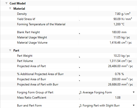
Additional values are calculated based on the input values for the part and shown at the process
| Part Property | Group | Calculated Value |
|---|---|---|
| Part Weight | Material |
|
| Part | Part Volume | |
| Projected Area of Part | Part |
Projected Area of Part with Burr |
| Forming Work |
Main Deformation |
Step 5: Insert Machine
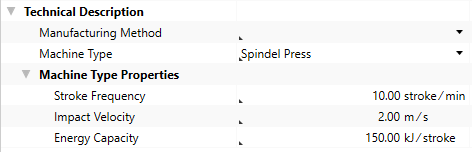
To calculate the necessary press force, values must be entered at the machine for the Machine Type, Stroke Frequency, Impact Velocity and Energy Capacity properties.
You can insert
The latter is shown in the following, because it illustrates the inputs required for calculation.
Insert Local Machine
- Select the »Die Forging« process in the Structure view.
- Click on Edit ► Insert ►
 Insert New Local Machine in the ribbon.
A machine is inserted under the »Die Forging« process.
- Change the label to »Die Forging Machine«.
- Under Details ► Technical Description ► Machine Type, select a machine type for the »Die Forging Machine«.Note
You can use the following
- Spindle Press
- Drop Hammer
- Impact Hammer
- Steam Powered Accelerated Hammer
The Machine Type Properties group appears under Technical Description.
- In the Details ► Technical Description view, enter a value for the following properties:
- Stroke Frequency
- Impact Velocity
- Energy Capacity
- Define the following properties for the
Acquisition Costs Acquisition Value 400,000 EURFixed Machine Costs Depreciation Period 6 a
Calculated values of the Die Forging cost model:
The following values are calculated using the data entered and then shown in the Details ► General ► Cost Model view:
- Cycle Time
- Ʃ Measure Values Cycle Time
- Cycles per Time
- Output per Cycle
- Output per Time
- Time per Unit Output
- Manufacturing Scrap Rate
- Production Cost
Step 6: Insert Worker and Tool
Insert Worker
- In the Structure view, select the
- In the ribbon, click on Edit ► Insert ►
 Worker.
The corresponding labor costs for the worker are determined based on the sector, the reference location, the reference date and the labor group.
Insert Tool
- In the Structure view, select the process
- Click Edit ► Insert ►
 Insert New Local Tool.
The tool is inserted under the process.
Step 7: Additional Fine Tuning
You can continue fine tuning the settings in the Details ► General ► Cost Model view:
| Group | Properties |
|---|---|
| Material |
|
| Forming Work |
|
| Machine |
|
| Secondary Processing Times |
|
| Primary Processing Times |
|
Properties of the Cost Model - Die Forging
Material Group
The material properties used to calculate the cost model are shown in this group.
| Material Properties | Description | Input Possible |
Calculated |
Required |
|---|---|---|---|---|
| Density |
Density of the material This value is required and can be managed at the material (Details View ► Technical Description), or is applied when global templates are inserted. |
x | ||
| Yield Stress kf |
Yield stress kf of the material depending on deformation rate at a given deformation temperature.
|
with F12 | x | |
| Deformation Temperature of the Material |
Temperature of the material during the forming process This value is required and can be managed at the material (Details View ► Technical Description) or is applied when global templates are inserted. |
x | ||
| Blank Part Height |
Height of the material before working (initial height). This value is required in order to calculate the deformation rate. |
direct | x | |
| Material Usage Weight |
Required material mass of the blank part
|
x | ||
| Material Usage Volume |
Required material volume of the blank part
|
x | ||
| Tensile Strength | Tensile strength of the material | direct |
Part Group
The part properties used to calculate the cost model are shown in this group.
| Part Properties | Description | Input Possible |
Calculated |
Required |
|---|---|---|---|---|
| Part Weight | Weight of the finished part | direct | x | |
| Part Volume |
Volume of the finished part
|
x | ||
| Projected Area of Part | The area of the part projected in the mold parting surface |
direct | x | |
| % Additional Project Area of Burr | Percentaged additional projected area of burr in relation to the projected part area |
direct | ||
| Projected Area of Burr | The projected area of the burr of the part | direct | x | |
| Projected Area of Part with Burr |
Projected area of the part incl. burr
|
x | ||
| Forging Form Group of Part |
Selection of form group for determination of mass ratio coefficient »1: Simple Forging Form«, e.g. parts like a sphere, cylinder or cube, perhaps with single-side variant or small flanges »2: Average Forging Form«, e.g. for rotationally symmetric parts with flange or single side forming and parts with punched holes or thin-walled joints to the outer diameter »3: Complex Forging Form«, e.g. two-armed, thin-walled levers with thickening in the middle and at the end of part and long parts with multiple cross-section transitions |
direct | x | |
| Mass Ratio Coefficient | Factor depending on the forging form group and the material usage weight | with F12 | ||
| Burr and Part Form |
Selection of burr in relation to the part »1: Forging Part without Burr«, compression in a forging die without burr »2: Forging Part with Slight Burr«, compression in a forging die with a slight burr »3: Forging Part with Burr«, compression of simple parts with burr »4: Complex Forging Part with Burr«, compression of complex parts with burr |
direct | x |
Forming Work Group
The forming work properties used to calculate the cost model are shown in this group.
| Forming Work Properties | Description | Input Possible |
Calculated |
Required |
|---|---|---|---|---|
| Deformation Rate |
Speed for forming the material
|
with F12 | ||
| Main Deformation |
Average deformation using the average target height
|
x | ||
| Deformation Efficiency |
Efficiency of the deformation work
|
x | ||
| Deformation Work |
Theoretical deformation work needed to manufacture the part
|
x | ||
| % Additional Deformation Work | Percentaged Additional Deformation Work | direct | ||
| Additional Deformation Work | Absolute additional deformation work Calculated when entering a value for the % additional deformation work |
direct | ||
| Required Deformation Work |
Deformation work that is actually required
|
x | ||
| Number of Strokes |
The number of strokes for production of all parts inside the die
|
with F12 |
Machine
The machine properties used to calculate the cost model are shown in this group.
| Machine Properties | Description | Input Possible |
Calculated |
Required |
|---|---|---|---|---|
| Machine Type | Assignment of a machine to a specific group with the corresponding properties This value is required in order to manage additional machine type properties. It can be managed at the machine (Details view ► Technical Description), or is applied when global templates are inserted. |
x | ||
| Impact Velocity |
The velocity of the forging tool impact at the die or part This value is required and can be managed at the machine (Details View ► Technical Description ► Machine Type Properties), or is applied when global templates are inserted. |
x | ||
| Energy Capacity of the Machine |
Machine energy capacity with one stroke This value is required and can be managed at the machine (Details View ► Technical Description ► Machine Type Properties), or is applied when global templates are inserted. |
x | ||
| Stroke Frequency of the Machine |
Maximum stroke frequency of the machine that is available This value is required and can be managed at the machine (Details View ► Technical Description ► Machine Type Properties), or is applied when global templates are inserted. |
x | ||
| Relative Stroke Frequency | Share of the stroke frequency that is actually used | direct | ||
| Relevant Stroke Frequency |
Stroke frequency that is actually used
|
with F12 | ||
| Time per Stroke |
Time required for a machine stroke
|
x |
Secondary Processing Times
The secondary processing times used to calculate the cost model are shown in this group.
| Secondary Processing Times | Description | Input Possible |
Calculated |
Required |
|---|---|---|---|---|
| Loading Time | Time for loading the machine with a part | direct | ||
| Unloading Time | Time for unloading the machine with a part | direct | ||
| Transfer Time between Strokes | Additional time between strokes | direct | ||
| Secondary Processing Time |
Necessary idle times of a process in which the actual activity of a process are not performed
|
x |
Primary Processing Times
The primary processing times used to calculate the cost model are shown in this group.
| Primary Processing Times | Description | Input Possible |
Calculated |
Required |
|---|---|---|---|---|
| Press Time |
Time to press all strokes
|
x | ||
| Additional Primary Processing Times | Chance to add primary processing times that have not been considered yet | direct | ||
| Primary Processing Time |
Time in which the actual activity of a process is performed.
|
x |