Cost Model - Deep Drawing
You can use the Deep Drawing cost model to calculate the process times and costs for the deep drawing manufacturing process in plastics processing. In FACTON, there are value rule tables, and at the cost model formulas are defined that provide you with information on:
- The anticipated cycle time,
- the possible process output per time and cycle,
- the material consumption,
- the press force and stroke frequency of the machine and
- the primary and secondary processing times.
You need knowledge of the
Procedure
The following example illustrates the process and structure of the
The black triangle helps you identify values that you can enter ![]() .
.
The Consistency Rule Violation check is available to you when entering values. The consistency rule violations check notifies you of missing values and verifies the accuracy of the values entered.
When you hover over one of the Consistency rule violations icons with your mouse, a tooltip appears with the specific reason for the consistency rule violations.
Step 1: Create Should Cost Calculation
Create
- You are logged in as Calculator.
- You are in the Calculations workspace.
- In the ribbon, click on Manage.
- Select the
 Should Cost Calculation
The created calculation opens in a new tab.
You are the owner of the calculation that was created.
- Define the following properties for the Should Cost Calculation in the Details view:
- Material Overhead Rate
- Manufacturing Overhead Rate
- Administrative Overhead Rate
- Sales Overhead Rate
- Development Overhead Rate
- Logistics Overhead Rate
| Reference Company* | |
| Industrial Sector |
|
| Production Location | World » Europe » Germany |
| Reference Company Plant Revenue | 100m EUR |
| Reference Company Material Share | 50% |
| Reference Company Degree of Automation | Medium |
| Production Planning | |
| Production Quantity | 100,000 pc / a |
| Target Profit Rates | |
| Target Profit Rate on Raw Material | 2 % |
| Target Profit Rate on Purchased Material | 2 % |
| Target Profit Rate on Manufacturing | 2 % |
|
* Values are determined for the following properties using value rules based on your inputs under reference companies: |
|
Step 2: Insert Process
Insert Process
- In the Structure view, select the calculation element you wish to insert under the process.
- Click Edit ► Insert ►
 Process in the ribbon.
A process is inserted in the calculation structure.
- Change the label to
- Define the following properties for the process in the Details view:
- In the Details ► General ► Valuation view, select the valuation Cost Model:
A new Cost Model group appears with subgroups.
| Technical Descriptions | |
| Material Classification* |
|
| Manufacturing Method* |
|
| * FACTON recommends the appropriate materials and machines in the queries for the processes by allowing you to select the material classification and manufacturing process. | |
When changing valuations the sub-elements are grayed-out and no longer considered in the calculation.
Step 3: Insert Material
Values must be entered at the material for the Material Thickness, Material Classification and the Tensile Strength properties in order to calculate the primary processing times.
Values are determined for the following properties using value rules by selecting the material classification:
- Squared Material Factor (for Drawing Clearance)
You can view the properties under Details ► General ► Cost Model ► Material.
You can insert
The latter is shown in the following, because it illustrates the inputs required for calculation.
Insert Local Material
- Select the »Deep Drawing« process in the Structure view.
- Click on Edit ► Insert ►
 Insert New Local Material (Mass).
A local material is inserted under the »Deep Drawing« process.
- Change the label to »Deep Drawing Material«.
- In the Details ► General ► Valuation view, select the valuation Sheet.Note
Only the following combinations of Valuation and Geometric Shape are supported for the Deep Drawing cost model. Depending on the valuation you choose, you may see different material properties or you may be required to enter different information.
Valuation Geometric Shape Required Input (Material Thickness) Solid Profile Flat Height (s) Coil Strip Strip Thickness Sheet Sheet Sheet Thickness Selecting this valuation creates a new group Form Type & Geometry with additional material properties.
- In the Form Type & Geometry group, select the geometric shape Sheet.
Sheet width and sheet thickness will be displayed as additional material properties.
- Enter a value for the Sheet Thickness (e.g. 1.6 mm).
This value is required and displayed at the »Deep Drawing« process in the Details ► General ► Cost Model ► Material view under Material Thickness.
- Under Details ► Technical Description ► Material Classification, select a material classification (e.g. Basic Materials > Metal > Steel).Note
You can use the following
All material classifications under »Metals« and »Plastics«. You can enter the tensile strength for these materials.
The Material Classification Properties group appears under Technical Description.
- Enter a value for the Tensile Strength (e.g. 600 N/mm²).
This value is required and displayed at the »Deep Drawing« process in the Details ► General ► Cost Model ► Material view under Tensile Strength.
- Define the following properties for the
General Price per Unit  0.75 EUR / kg
 - Select the »Deep Drawing« process in the Structure view.
- Enter a value in the Details ► Cost Model ► Material ► Sheet Metal Blank Area view (e.g. 2,042,035 mm²).
Step 4: Describe Part
The part properties are required to determine the cycle time.
Describe Part
- In the Structure view, select the process
- Enter the following values for the part in the Details ► Cost Model ► Part view.
These values are required in order to calculate additional values:
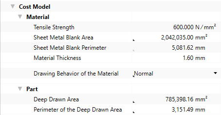
Additional values are calculated based on the input values for the part and shown at the process
Step 5: Insert Work Steps
The Deep Drawing process requires a wide range of individual work steps in order to manufacture a part. To visualize complex deep drawing parts in detail, they must be broken down into separate work steps.
With FACTON, you can define multiple work steps at the Deep Drawing cost model.
Insert Work Steps
- Select the »Deep Drawing« process in the Structure view.
- In the Details view, open the group Cost Model ► Work Steps.
- Click on the
 button next to the Value column in the Drawing Work Steps row.
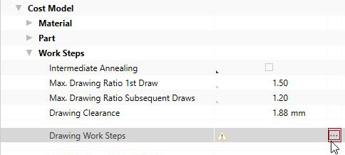
The Local List: Drawing Work Steps tab opens.
For more information on the work step, see:Work Step Properties
- Right-click in the empty area of the tab ►
 New.
New.A new row is added for you to define your work step.
- Change the label to »1st Draw«
- Repeat step 4.
- Change the label to »2nd Draw«
General group
This group shows the general work step properties.
| Properties | Description | Input Possible |
Calculated |
Required |
|---|---|---|---|---|
| Label | Work Step Name | direct | x | |
| Initial Area | The surface area of the part region before the draw Corresponds to the value for the Area of the Sheet Metal Blank. |
with F12 | x | |
| Deep Drawn Area | Area to be deep drawn in this step | with F12 | x | |
| Perimeter of the Deep Drawn Area | Perimeter of the areas to be deep drawn in this step | with F12 | x | |
| Actual Drawing Ratio |
Actual drawing ratio of the deep drawing surfaces before and after the drawing work step
|
x | ||
| Allowable Drawing Ratio |
Maximum allowable ratio of the deep drawing surfaces before and after the drawing work step
|
|||
| Min. Deep Drawing Area |
Minimum size of the deep drawing area after the drawing work step
|
with F12 | x | |
| Draw Correction Factor |
Factor for determining the deep drawing force depending on the drawing ratios
|
x | ||
| Theoretical Press Force |
Calculated press force for this work step
|
x | ||
| Drawing Corner Radius |
The drawing corner radius prevents the wrinkling or tearing of the material
|
with F12 | x | |
| Blank holder Area |
The area of the material, which has to be held during the deep drawing in order to avoid wrinkling
|
with F12 | ||
| Blank holder Pressure |
The pressure with which the blankholder area has to be held
|
with F12 | ||
| Blank holder Force |
The force with which the blankholder area has to be held
|
x | ||
| % Additional Press Force | Percentaged additional press force Calculated when you enter a value for the surcharge for press force. |
direct | ||
| Additional Press Force | Absolute additional press force Calculated when you enter a value for the percentaged additional press force |
direct | ||
| Necessary Press Force |
Necessary total press force for this work step
|
x |
Technical Description Group
The technical descriptions of the work step, such as name and description, are shown and managed in this group.
Step 6: Insert Machine
You can use the Relevant Press Force from the work steps to determine and insert the required machine.
For calculating the press time and time per stroke, values must be entered at the machine for the Machine Type, Press Force and Stroke Frequency properties.
You can insert
The latter is shown in the following, because it illustrates the inputs required for calculation.
Insert Local Machine
- Select the »Deep Drawing« process in the Structure view.
- Click on Edit ► Insert ►
 Insert New Local Machine in the ribbon.
A machine is inserted under the »Deep Drawing« process.
- Change the label to »Deep Drawing Machine«.
- Under Details ► Technical Description ► Machine Type, select a machine type for the »Deep Drawing Machine«.Note
You can use the following
- Transfer Press
- C-Frame Press
- Deep Drawing Press
- 4-Column Press
- Toggle Press
The Machine Type Properties group appears under Technical Description.
- In the Details ► Technical Description view, enter a value for the following properties:
- Press Force
- Stroke Frequency
- Number of Press Stations
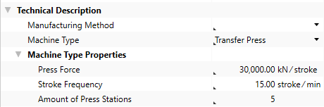
This entry is used to calculate the relevant stroke frequency.
- Define the following properties for the
Acquisition Costs Acquisition Value 3,500,000 EURFixed Machine Costs Depreciation Period 6 a
Calculated values of the Deep Drawing cost model:
The following values are calculated using the data entered and then shown in the Details ► General ► Cost Model view:
- Cycle Time
- Ʃ Measure Values Cycle Time
- Cycles per Time
- Output per Cycle
- Output per Time
- Time per Unit Output
- Manufacturing Scrap Rate
- Production Cost
Step 7: Insert Worker and Tool
Insert Worker
- In the Structure view, select the
- In the ribbon, click on Edit ► Insert ►
 Worker.
The corresponding labor costs for the worker are determined based on the sector, the reference location, the reference date and the labor group.
Insert Tool
- In the Structure view, select the process
- Click Edit ► Insert ►
 Insert New Local Tool.
The tool is inserted under the process.
Step 8: Additional Fine Tuning
You can continue fine tuning the settings in the Details ► General ► Cost Model view:
| Group | Properties |
|---|---|
| Material |
|
| Work Steps |
|
| Machine |
|
| Secondary Processing Times |
|
| Primary Processing Times |
|
Properties of the Cost Model - Deep Drawing
Material Group
The material properties used to calculate the cost model are shown in this group.
| Material Properties | Description | Input Possible |
Calculated |
Required |
|---|---|---|---|---|
| Tensile Strength |
Tensile strength of the material This value is required and can be managed at the material (Details View ► Technical Description), or is applied when global templates are inserted. |
with F12 | x | |
| Sheet Metal Blank Area | Sheet Metal Blank Area | direct | x | |
| Sheet Metal Blank Perimeter |
Perimeter of the sheet metal blank
The perimeter of the sheet metal blank is calculated based on a circular area. For other geometries value |
with F12 | ||
| Material Thickness | Thickness of the material used This value is required and can be managed at the material (Details View ► General ► Form Type & Geometry), or is applied when global templates are inserted. |
x | ||
| Drawing Behavior of the Material |
Variety of the drawing behavior of the material »Normal« |
direct | x |
Part Group
The part properties used to calculate the cost model are shown in this group.
| Part Properties | Description | Input Possible |
Calculated |
Required |
|---|---|---|---|---|
| Deep Drawn Area | Area that was deep drawn in this step | direct | x | |
| Perimeter of the Deep Drawn Area | Perimeter of the deep drawn area for this draw | direct | x |
Work Steps Group
The work step properties in the deep drawing process used to calculate the cost model are shown in this group.
| Work Step Properties | Description | Input Possible |
Calculated |
Required |
|---|---|---|---|---|
| Intermediate Annealing | Selection of intermediate annealing. The intermediate annealing allows a higher drawing ratio in the next drawing work step | direct | ||
| Max. Drawing Ratio 1st Draw |
The maximum drawing ratio in the 1st drawing work step
|
with F12 | ||
| Max. Drawing Ratio Subsequent Draws |
The max. drawing ratio from the 2nd drawing work step on
|
with F12 | ||
| Drawing Clearance |
Gap between the cavity and the drawing punch
|
x | ||
| Drawing Work Steps | Displays the work steps of the deep drawing process the |
x | ||
| Used Drawing Work Steps | Displays the number of used drawing work steps | |||
| Blanking of Sheet Metal Blank | Selection of additional blanking work steps within the process (e.g.: with a transfer tool / transfer machine). | direct | ||
| Max. Necessary Cutting Force | Maximum necessary cutting force of all work steps. | with F12 | ||
| Additional Work Steps Blanking | The number of work steps to be used for blanking. | with F12 | ||
| Additional Work Steps | The number of additional work steps, e.g. for the calibration or the control of the part | direct | ||
| Total Number of Required Work Steps | Displays the total number of work steps in this process | |||
| Parallel Processing | Displays, whether all work steps are carried out at the same time (e.g.: with a transfer tool / transfer machine) | with F12 | ||
| Number of Strokes | The number of strokes for production of all parts inside the die | x | ||
| Relevant Press Force | Displays the relevant press force incl. all surcharges | x |
Machine
The machine properties used to calculate the cost model are shown in this group.
| Machine Properties | Description | Input Possible |
Calculated |
Required |
|---|---|---|---|---|
| Machine Type | Assignment of a machine to a specific group with the corresponding properties This value is required in order to manage additional machine type properties. It can be managed at the machine (Details view ► Technical Description), or is applied when global templates are inserted. |
x | ||
| Press Force of the Machine |
Displays the maximum press force of the machine This value is required and can be managed at the machine (Details View ► Technical Description ► Machine Type Properties), or is applied when global templates are inserted. |
x | ||
| Stroke Frequency of the Machine |
Displays the maximum stroke frequency of the machine This value is required and can be managed at the machine (Details View ► Technical Description ► Machine Type Properties), or is applied when global templates are inserted. |
x | ||
| Relative Stroke Frequency | Share of the stroke frequency that is actually used | direct | ||
| Relevant Stroke Frequency |
Stroke frequency that is actually used
|
with F12 | ||
| Number of Press Stations |
Display the number of press stations |
x | ||
| Time per Stroke |
Time required for a machine stroke
|
x |
Secondary Processing Times
The secondary processing times used to calculate the cost model are shown in this group.
| Secondary Processing Times | Description | Input Possible |
Calculated |
Required |
|---|---|---|---|---|
| Loading Time | Time for loading the machine with a part | direct | ||
| Unloading Time | Time for unloading the machine with a part | direct | ||
| Machine Loading Per Stroke | Time to load the machine per stroke | direct | ||
| Machine Unloading per Stroke | Time to unload the machine per stroke | direct | ||
| Transfer Time between Strokes | Additional time between strokes | direct | ||
| Additional Secondary Processing Times | Possibility to add secondary processing times that have not been considered | direct | ||
| Secondary Processing Time |
Necessary idle times of a process in which the actual activity of a process are not performed
|
x |
Primary Processing Times
The primary processing times used to calculate the cost model are shown in this group.
| Primary Processing Times | Description | Input Possible |
Calculated |
Required |
|---|---|---|---|---|
| Press Time |
Time to press all strokes
|
x | ||
| Additional Primary Processing Times | Possibility to add primary processing times that have not been considered | direct | ||
| Primary Processing Time |
Time in which the actual activity of a process is performed.
|
x |