Cost Model - Blanking
You can use the Blanking cost model to calculate the process times and costs for the blanking manufacturing process. In FACTON, there are value rule tables, and at the cost model formulas are defined that provide you with information on:
- The anticipated cycle time,
- the possible process output per time and cycle,
- clamping force of the machine,
- material consumption and
- primary and secondary processing times.
Machines and material parameters are required for the calculation.
You need knowledge of the
Procedure
The following example illustrates the process and structure of the
The black triangle helps you identify values that you can enter ![]() .
.
The Consistency Rule Violation check is available to you when entering values. The consistency rule violations check notifies you of missing values and verifies the accuracy of the values entered.
When you hover over one of the Consistency rule violations icons with your mouse, a tooltip appears with the specific reason for the consistency rule violations.
Step 1: Create Should Cost Calculation
Create
- You are logged in as Calculator.
- You are in the Calculations workspace.
- In the ribbon, click on Manage.
- Select the
 Should Cost Calculation
The created calculation opens in a new tab.
You are the owner of the calculation that was created.
- Define the following properties for the Should Cost Calculation in the Details view:
- Material Overhead Rate
- Manufacturing Overhead Rate
- Administrative Overhead Rate
- Sales Overhead Rate
- Development Overhead Rate
- Logistics Overhead Rate
| Reference Company* | |
| Industrial Sector |
|
| Production Location | World » Europe » Germany |
| Reference Company Plant Revenue | 100m EUR |
| Reference Company Material Share | 50% |
| Reference Company Degree of Automation | Medium |
| Production Planning | |
| Production Quantity | 100,000 pc / a |
| Target Profit Rates | |
| Target Profit Rate on Raw Material | 2 % |
| Target Profit Rate on Purchased Material | 2 % |
| Target Profit Rate on Manufacturing | 2 % |
|
* Values are determined for the following properties using value rules based on your inputs under reference companies: |
|
Step 2: Insert Process
Insert Process
- In the Structure view, select the calculation element you wish to insert under the process.
- Click Edit ► Insert ►
 Process in the ribbon.
A process is inserted in the calculation structure.
- Change the label to
- Define the following properties for the process in the Details view:
- In the Details ► General ► Valuation view, select the valuation Cost Model:
A new Cost Model group appears with subgroups.
| Technical Descriptions | |
| Material Classification* |
|
| Manufacturing Method* |
|
| * FACTON recommends the appropriate materials and machines in the queries for the processes by allowing you to select the material classification and manufacturing process. | |
When changing valuations the sub-elements are grayed-out and no longer considered in the calculation.
Step 3: Insert Material
Values must be entered at the material for Material Thickness and Tensile Strength in order to calculate the relevant stroke frequency and maximum shear strength.
You can insert
The latter is shown in the following, because it illustrates the inputs required for calculation.
Insert Local Material
- Select the »Blanking« process in the Structure view.
- Click on Edit ► Insert ►
 Insert New Local Material (Mass) in the ribbon.
A local material is inserted under the »Blanking« process.
- Change the label to »Blanking Material«
- In the Details ► General ► Valuation view, select Sheet.Note
Only the following combinations of »Valuation« and »Geometric Shape« are supported for the Blanking cost model. Depending on the chosen valuation, you may see different material properties or you may be required to enter different information.
Valuation Geometric Shape Required Input (Material Thickness) Solid Profile Flat Height (s) Coil Strip Strip Thickness Sheet Sheet Sheet Thickness Selecting this valuation creates a new property group Form Type & Geometry with additional material properties.
- In the Form Type & Geometry group, select the geometric shape Sheet.
Sheet width and sheet thickness will be displayed as additional material properties.
- Enter a value for the Sheet Thickness (e.g. 2 mm).
This value is required, and it is displayed at the »Blanking« process in the Details ► General ► Cost Model ► Material view under Material.
- Under Details ► Technical Description ► Material Classification, select a material classification (e.g. Basic Materials » Metal » Steel).Note
You can use the following
All material classifications under »Metals« and »Plastics«. You can enter the tensile strength for these materials.
The Material Classification Properties group appears under Technical Description.
- Under Technical Description , enter a value for the Tensile Strength.
This value is required, and it is displayed at the »Blanking« process in the Details ► General ► Cost Model ► Material view under Tensile Strength. The maximum shear strength is calculated based on the tensile strength. - Define the following properties for the
General Price per Unit  0.75 EUR / kg
You can define further properties for the sheet material, such as sheet width, sheet length, and output per sheet in the Details view. This data is used for calculating the cross-sectional area, volume, gross weight, and weight per length.
Step 4: Insert Work Steps
The Blanking process requires a wide range of individual work steps in order to manufacture a part. To visualize complex blanking parts in detail, they must be split into separate work steps.
With FACTON, you can define multiple work steps at the Blanking cost model.
Insert Work Steps
- Select the »Blanking« process in the Structure view.
- In the Details view, open the group Cost Model ► Work Steps.
- Click on the
 button next to the Value column in the Work Steps row.
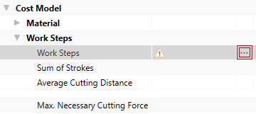
The Local List : Work Steps tab opens.
Further information on the work steps, see:Work Step Properties
- Right-click in the empty area of the tab ►
 New.
New.A new row is added for you to define your work step.
- In the Local List view enter a value for the following properties of the work step:
- Label
- Cutting Length
- Cutting Distance
- Number of Cuts
- Additional Cutting Force
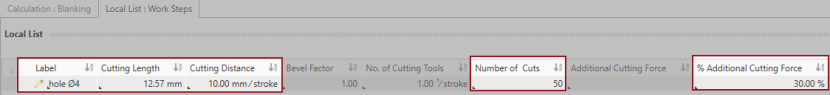
These values are required in order to calculate additional values.
| Work Step Properties | Cost Model Group | Calculated Value |
|---|---|---|
| Cutting Length | Primary Processing Times | Theoretical Cutting Force |
| Number of Cuts | Number of Strokes | |
| Cutting Length | Work Steps | Max. Necessary Cutting Force |
| Cutting Distance | Average Cutting Distance | |
| Number of Cuts | Sum of Strokes |
General Group
This group shows the general work step properties, such as Label.
Primary Processing Times Group
This group shows the primary processing times for the work step.
| Properties | Description | Input Possible |
Calculated |
Required |
|---|---|---|---|---|
| Cutting Length | The length of the cutting edge or contour of the workpiece, which is machined in the work step or the total length cut by the tool. This value is required. |
direct | x | |
| Cutting Distance | Distance to the next hole or cut (e.g. hole spacing) This value is required. |
direct | x | |
| Bevel Factor | The bevel at a cutting tool reduces the press force. If no bevel is available, the value is »1«. | direct |
|
|
| Number of Cutting Tools | The number of the cutting stamps / tools that are used simultaneously during a machine stroke | direct | ||
| Number of Cuts | Number of required cuts for this work step. This value is required. | direct | x | |
| Number of Strokes |
The number of strokes for the production of all cuts in this work step
|
x | ||
| Theoretical Cutting Force |
Calculated cutting force for this work step
|
x | ||
| % Additional Cutting Force | Percentaged additional cutting force is calculated, when entering a value for the additional cutting force. |
direct | ||
| Additional Cutting Force | Absolute additional cutting force is calculated, when entering a value for the % additional cutting force |
direct | ||
| Necessary Cutting Force |
Necessary cutting force for a machine stroke in this work step
|
x |
Secondary Processing Times Group
This group shows the secondary processing times for the work step.
| Properties | Description | Input Possible |
Calculated |
Required |
|---|---|---|---|---|
| Tool Changes | Selection whether time is required for changing the tool or not. | direct |
|
|
| Tool Change Time | Shows the time to change a tool. | with F12 |
Technical Description Group
The technical descriptions of the work step, such as label and description, are shown and managed in this group.
Step 5: Insert Machine
You can use the calculated maximum Necessary Cutting Force from the work steps to determine the required machine and insert it.
Values must be entered at the machine for Press Force and Stroke Frequency to calculate the cutting pressure (blanking) and speed.
You can insert
The latter is shown in the following, because it illustrates the inputs required for calculation.
Insert Local Machine
- Select the »Blanking« process in the Structure view.
- Click on Edit ► Insert ►
 Insert New Local Machine in the ribbon.
A machine is inserted under the »Blanking« process.
- Change the label to »Blanking Machine«.
- Under Details ► Technical Description ► Machine Type, select a machine type for the »Blanking Machine«.Note
You can use the following
- Fine Blanking Press
- Toggle Press
- Blanking Line
- Transfer Press
- Swing Beam Machine
The Machine Type Properties group appears under Technical Description.
- In the Details ► Technical Description ► Machine Type Properties view, enter a value for the following properties:
- Press Force
- Stroke Frequency
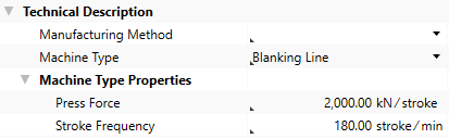
This entry is used for calculating the relevant stroke frequency.
- Define the following properties for the
Acquisition Cost Purchase Value 200,000 EURFixed Machine Cost Depreciation Period 6 a
Calculated values of the Blanking cost model:
The following values are calculated using the data entered and then shown in the Details ► General ► Cost Model view:
- Cycle Time
- Ʃ Measure Values Cycle Time
- Cycles per Time
- Output per Cycle
- Output per Time
- Time per Unit Output
- Manufacturing Scrap Rate
- Production Cost
Step 6: Insert Worker and Tool
Insert Worker
- In the Structure view, select the
- In the ribbon, click on Edit ► Insert ►
 Worker.
The corresponding labor costs for the worker are determined based on the sector, the reference location, the reference date and the labor group.
Insert Tool
- In the Structure view, select the process
- Click Edit ► Insert ►
 Insert New Local Tool.
The tool is inserted under the process.
Step 7: Additional Fine Tuning
You can continue fine tuning the settings in the Details ► General ► Cost Model view:
| Group | Properties |
|---|---|
| Work Steps ► Local List |
|
| Secondary Processing Times |
|
| Primary Processing Times |
Additional Primary Processing Times |
Properties of the Cost Model - Blanking
Material Group
The material properties used to calculate the cost model are shown in this group.
| Material Properties | Description | Input Possible |
Calculated |
Required |
|---|---|---|---|---|
| Tensile Strength |
Tensile strength of the material This value is required and can be managed at the material (Details View ► Technical Description) or is applied when global templates are inserted. |
x | ||
| Factor for Max. Shear Strength | The factor for max. shear strength, is usually entered with »0.8«. | with F12 | ||
| Max. Shear Strength |
Maximum shear strength of the material
|
x | ||
| Material Thickness | Thickness of the material used This value is required and can be managed at the material (Details View ► General ► Form Type & Geometry) or is applied when global templates are inserted. |
x |
Work Steps Group
The work step properties in the deep drawing process used to calculate the cost model are shown in this group.
| Work Step Properties | Description | Input Possible |
Calculated |
Required |
|---|---|---|---|---|
| Work Steps | Displays the work steps of the blanking process The |
x | ||
| Sum of Strokes | Sum of the strokes of all work steps | x | ||
| Average Cutting Distance |
Average cutting distance of all work steps
|
x | ||
| Max. Necessary Cutting Force | Maximum necessary cutting force of all work steps. | x |
Machine
The machine properties used to calculate the cost model are shown in this group.
| Machine Properties | Description | Input Possible |
Calculated |
Required |
|---|---|---|---|---|
| Machine Type | Assignment of a machine to a specific group with the corresponding properties This value is required in order to manage additional machine type properties. It can be managed at the machine (Details view ► Technical Description), or is applied when global templates are inserted. |
directly at the machine | x | |
| Press Force of the Machine |
Displays the maximum press force of the machine This value is required and can be managed at the machine (Details View ► Technical Description ► Machine Type Properties), or is applied when global templates are inserted. |
directly at the machine | x | |
| Stroke Frequency of the Machine |
Displays the maximum stroke frequency of the machine This value is required and can be managed at the machine (Details View ► Technical Description ► Machine Type Properties), or is applied when global templates are inserted. |
directly at the machine | x | |
| Relevant Stroke Frequency |
Effective stroke frequency
|
with F12 | ||
| Tool Change Time |
Time to change a tool
|
with F12 |
Secondary Processing Times
The secondary processing times used to calculate the cost model are shown in this group.
| Secondary Processing Times | Description | Input Possible |
Calculated |
Required |
|---|---|---|---|---|
| Loading and Unloading Time | Time for loading and unloading the machine with a workpiece. | direct | ||
| Summed Tool Change Time | The sum of the tool changing time of all work steps | x | ||
| Additional Secondary Processing Times | Possibility to add secondary processing times that have not been considered | direct | ||
| Secondary Processing Time |
Necessary idle times of a process in which the actual activity of a process are not performed
|
x |
Primary Processing Times
The primary processing times used to calculate the cost model are shown in this group.
| Primary Processing Times | Description | Input Possible |
Calculated |
Required |
|---|---|---|---|---|
| Additional Primary Processing Times | Possibility to add primary processing times that have not been considered | direct | ||
| Primary Processing Time |
Time in which the actual activity of a process is performed.
|
x |