Cost Model - Extrusion
You can use the Extrusion cost model to calculate the process times and costs for the extrusion manufacturing process in metalworking. In FACTON, there are value rule tables, and at the cost model there are formulas defined that offer you information on:
- The anticipated cycle time,
- the possible process output per time and cycle,
- the material consumption,
- the press force and stroke frequency of the machine and
- primary and secondary processing times.
In the cost model Extrusion a distinction is made between direct extrusion and indirect extrusion.
You need knowledge of the Extrusion manufacturing process in order to use the cost model.
Procedure
The following example illustrates the process and structure of the Extrusion cost model.
The black triangle helps you identify values that you can enter ![]() .
.
The Consistency Rule Violation check is available to you when entering values. The consistency rule violations check notifies you of missing values and verifies the accuracy of the values entered.
When you hover over one of the Consistency rule violations icons with your mouse, a tooltip appears with the specific reason for the consistency rule violations.
Step 1: Create Should Cost Calculation
Create Calculation
- You are logged in as Calculator.
- You are in the Calculations workspace.
- In the ribbon, click on Manage.
- Select the
 Should Cost Calculation
The created calculation opens in a new tab.
You are the owner of the calculation that was created.
- Define the following properties for the Should Cost Calculation in the Details view:
- Material Overhead Rate
- Manufacturing Overhead Rate
- Administrative Overhead Rate
- Sales Overhead Rate
- Development Overhead Rate
- Logistics Overhead Rate
| Reference Company* | |
| Industrial Sector |
|
| Production Location | World » Europe » Germany |
| Reference Company Revenue | 100m EUR |
| Reference Company Material Share | 50% |
| Reference Company Degree of Automation | Medium |
| Production Planning | |
| Production Quantity | 100,000 pc / a |
| Target Profit Rates | |
| Target Profit Rate on Raw Material | 2 % |
| Target Profit Rate on Purchased Material | 2 % |
| Target Profit Rate on Manufacturing | 2 % |
|
* Values are determined for the following properties using value rules based on your inputs under reference companies: |
|
Step 2: Insert Process
Insert Process
- In the Structure view, select the calculation element you wish to insert under the process.
- Click Edit ► Insert ►
 Process in the ribbon.
A process is inserted in the calculation structure.
- Change the label to
- Define the following properties for the process in the Details view:
- In the Details ► General ► Valuation view, select the valuation Cost Model:
A new Cost Model group appears with subgroups.
| Technical Descriptions | |
| Material Classification* |
|
| Manufacturing Method* |
|
| * FACTON recommends the appropriate materials and machines in the queries for the processes by allowing you to select the material classification and manufacturing process. | |
When changing valuations the sub-elements are greyed-out and no longer considered in the calculation.
For more information on the Extrusion cost model, see: Cost Model Properties
Step 3: Insert Material
Values must be entered at the material for the Density and the Material Classification properties for the calculation.
Values are determined for the following properties using value rules by selecting the material classification:
- Yield Stress Before Working
- Yield Stress at 100% Reduction Ratio
- Strain Hardening Exponent
- Allowable Deformation
You can view the properties under Details ► General ► Cost Model ► Material.
You can insert
The latter is shown in the following, because it illustrates the inputs required for calculation.
Insert Local Material
- Select the »Extrusion« process in the Structure view.
- Click on Edit ► Insert ►
 Insert New Local Material (Mass) in the ribbon.
A local material is inserted under the »Extrusion« process.
- Change the label to »Extrusion Material«.
- In the Details ► Technical Description view, enter a value for the Density (e.g. 7.85 kg/cm³).
- Under Details ► Technical Description ► Material Classification, select a material classification.Note
You can use the following material classifications with the cost model:
- Alloyed Steel / Construction Steel / Chemical Resistant Steel
- Steel with Special Physical Properties
- Stainless Steel Unalloyed
- Tool Steel
- Quality Steel Alloyed
- Quality Steel Unalloyed
- Basic Steel
- Aluminum
- Copper
- Define the following property in the Details view:
General Price per Unit  0.50 EUR / kg
 - Select the »Extrusion« process in the Structure view.
- Enter a value in the Details ► Cost Model ► Material ► Cross-Sectional Area of Blank view (e.g. 1.661 mm²).
The Material Classification Properties group appears under Technical Description.
Step 4: Describe Part
The part properties are required in order to determine the cycle time.
Describe Part
- In the Structure view, select the process
- Enter the following values for the part in the Details ► Cost Model ► Part view.
These values are required in order to calculate additional values:
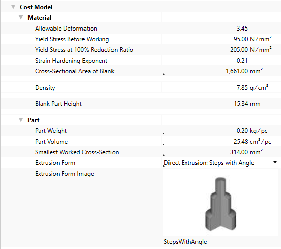
Additional values are calculated based on the input values for the part and shown at the process
Step 5: Insert Work Steps
The Extrusion process requires a wide range of individual work steps in order to manufacture a part. To visualize complex extrusion parts in detail, they must be broken down into separate work steps.
With FACTON, you can define multiple work steps at the Extrusion cost model.
Insert Work Steps
- Select the »Extrusion« process in the Structure view.
- In the Details view, open the group Cost Model ► Work Steps.
- Click on the
 button next to the Value column in the Press Work Steps row.
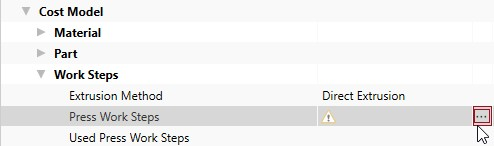
The Local List: Press Work Steps tab opens.
For more information on the work step, see:Work Step Properties
- Right-click in the empty area of the tab ►
 New.
New.A new row is added for you to define your work step.
- Change the label to »Pressing 1«
General Group
This group shows the general work step properties.
| Properties | Description | Input Possible |
Calculated |
Required |
|---|---|---|---|---|
| Name | Work Step Name | direct | x | |
| Initial Cross-Section | The cross-sectional area of the component before the impact extrusion step Corresponds to the value for the Cross-Sectional Area of Blank |
with F12 | x | |
| Target Cross-Section | Cross-sectional area of the worked part | with F12 | x | |
| Actual Deformation |
Actual drawing ratio of the extrusion surfaces before and after the extrusion work step
|
x | ||
| Allowable Deformation | The maximum allowable ratio of the cross-section to be deformed 'before' and 'after' the work step. | with F12 | ||
| Min. Cross-Section |
Indicates the minimum size of the cross-sectional area depending on the allowable change in shape
|
x | ||
| Theoretical Press Force |
Calculated press force for this work step
|
x | ||
| % Additional Press Force | Percentaged additional press force Calculated when entering a value for the surcharge for press force. |
direct | ||
| Additional Press Force | Absolute additional press force Calculated when entering a value for the percentaged additional press force |
direct | ||
| Necessary Press Force |
Necessary total press force for this work step
|
x | ||
| Extrusion Deformation Efficiency | Describes the loss of force during extrusion due to the friction on the press tool as well as the displacements within the material | with F12 | ||
| Yield Stress at the End of the Working | The yield stress of the material on reaching the actual reduction ratio | x | ||
| Average Yield Stress | Is the average value of the yield stress of the material 'before' and 'after' working | x |
Technical Description Group
The technical descriptions of the work step, such as name and description, are shown and managed in this group.
Step 6: Insert Machine
You can use the Relevant Press Force from the work steps to determine and insert the required machine.
To calculate the press time and time per stroke, values must be entered at the machine for the Machine Type, Press Force and Stroke Frequency properties.
You can insert
The latter is shown in the following, because it illustrates the inputs required for calculation.
Insert Local Machine
- Select the »Extrusion« process in the Structure view.
- Click on Edit ► Insert ►
 Insert New Local Machine in the ribbon.
A machine is inserted under the »Extrusion« process.
- Change the label to »Extrusion Machine«.
- Under Details ► Technical Description ► Machine Type, select a machine type for the »Extrusion Machine«.Note
You can use the following machine types with the cost model:
- Transfer Press
- C-Frame Press
- 4-Column Press
- Toggle Press
The Machine Type Properties group appears under Technical Description.
- In the Details ► Technical Description view, enter a value for the following properties:
- Press Force
- Stroke Frequency
- Number of Press Stations
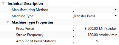
This entry is used to calculate the relevant stroke frequency.
- Define the following properties for the machine in the Details view:
Acquisition Costs Acquisition Value 1,500,000 EURFixed Machine Costs Depreciation Period 6 a
Calculated values of the Extrusion cost model:
The following values are calculated using the data entered and then shown in the Details ► General ► Cost Model view:
- Cycle Time
- Ʃ Measure Values Cycle Time
- Cycles per Time
- Output per Cycle
- Output per Time
- Time per Unit Output
- Manufacturing Scrap Rate
- Production Cost
Step 7: Insert Worker and Tool
Insert Worker
- In the Structure view, select the
- In the ribbon, click on Edit ► Insert ►
 Worker.
The corresponding labor costs for the worker are determined based on the sector, the reference location, the reference date and the labor group.
Insert Tool
- In the Structure view, select the process
- Click Edit ► Insert ►
 Insert New Local Tool.
The tool is inserted under the process.
Step 8: Additional Fine Tuning
You can continue fine tuning the settings in the Details ► General ► Cost Model view:
| Group | Properties |
|---|---|
| Work Steps |
|
| Machine |
|
| Secondary Processing Times |
|
| Primary Processing Times |
|
Cost Model Properties
Material Group
The material properties used to calculate the cost model are shown in this group.
| Material Properties | Description | Input Possible |
Calculated |
Required |
|---|---|---|---|---|
| Allowable Deformation |
Tensile strength of the material This value is required and can be managed at the material (Details View ► Technical Description), or is applied when global templates are inserted. |
x | ||
| Yield Stress Before Working |
The yield stress of the material at reduction (extrusion) ratio 0%
|
x | ||
| Yield Stress at 100% Reduction Ratio |
Perimeter of the sheet metal blank
The perimeter of the sheet metal blank is calculated based on a circular area. For other geometries value |
x | ||
| Strain Hardening Exponent | Thickness of the material used This value is required and can be managed at the material (Details View ► General ► Form Type & Geometry), or is applied when global templates are inserted. |
x | ||
| Cross-Sectional Area of Blank |
Selection of the drawing behavior of the material Choose between: »Normal« |
Direct | x | |
| Density |
Density of the material This value is required and can be managed at the material (Details View ► Technical Description), or is applied when global templates are inserted. |
x | ||
| Blank Part Height | Height of the material before working (initial height) |
Part Group
The part properties used to calculate the cost model are shown in this group.
| Part Properties | Description | Input Possible |
Calculated |
Required |
|---|---|---|---|---|
| Part Weight | Weight of the part Is calculated when entering a value for the part volume |
Direct | x | |
| Part Volume | Volume of the part Is calculated when entering a value for the part weight |
Direct | x | |
| Smallest Worked Cross-Section | The smallest cross-sectional area of the component that is to be produced in this process | Direct | x | |
| Extrusion Form | Selection of the main characteristics of the part to be produced and the extrusion method | Direct | x | |
| Image of extrusion form | Shows a sample image of the selected extrusion form/mold |
Work Steps Group
The work step properties in the extrusion process used to calculate the cost model are shown in this group.
| Work Step Properties | Description | Input Possible |
Calculated |
Required |
|---|---|---|---|---|
| Extrusion Method |
Displays the extrusion method |
Direct | ||
| Press Work Steps | Displays the work steps of the extrusion process the |
x | ||
| Used Press Work Steps | Displays the number of used press work steps | |||
| Necessary Annealing Processes | Displays the number of annealing processes required during working | |||
| Additional Work Steps | The number of additional work steps, e.g. for the calibration or the control of the part | Direct | ||
| Total Number of Required Work Steps | Displays the total number of work steps in this process | |||
| Parallel Processing | Displays, whether all work steps are carried out at the same time (e.g.: with a transfer tool / transfer machine) | with F12 | ||
| Number of Strokes | The number of strokes for production of all parts inside the die | x | ||
| Relevant Press Force | Displays the relevant press force incl. all surcharges | x |
Machine Group
The machine properties used to calculate the cost model are shown in this group.
| Machine Properties | Description | Input Possible |
Calculated |
Required |
|---|---|---|---|---|
| Machine Type | Assignment of a machine to a specific group with the corresponding properties This value is required in order to manage additional machine type properties. It can be managed at the machine (Details view ► Technical Description), or is applied when master data is inserted. |
x | ||
| Press Force of the Machine | Displays the maximum press force of the machine This value is required and can be managed at the machine (Details View ► Technical Description ► Machine Type Properties), or is applied when master data is inserted. |
x | ||
| Stroke Frequency of the Machine | Displays the maximum stroke frequency of the machine This value is required and can be managed at the machine (Details View ► Technical Description ► Machine Type Properties), or is applied when master data is inserted. |
x | ||
| Relative Stroke Frequency | Share of the stroke frequency that is actually used | Direct | ||
| Relevant Stroke Frequency |
Stroke frequency that is actually used
|
with F12 | x | |
| Number of Press Stations |
Display the number of press stations |
x | ||
| Time per Stroke |
Time required for a machine stroke
|
x |
Secondary Processing Times Group
The secondary processing times used to calculate the cost model are shown in this group.
| Secondary Processing Times | Description | Input Possible |
Calculated |
Required |
|---|---|---|---|---|
| Loading Time | Time for loading the machine with a part | Direct | ||
| Unloading Time | Time for unloading the machine with a part | Direct | ||
| Machine Loading Per Stroke | Time to load the machine per stroke | Direct | ||
| Machine Unloading per Stroke | Time to unload the machine per stroke | Direct | ||
| Transfer Time between Strokes | Additional time between strokes | Direct | ||
| Additional Secondary Processing Times | Chance to add secondary processing times that have not been considered yet | Direct | ||
| Secondary Processing Time | Necessary idle times of a process in which the actual activity of a process are not performed is calculated from:
|
x |
Primary Processing Times Group
The primary processing times used to calculate the cost model are shown in this group.
| Primary Processing Times | Description | Input Possible |
Calculated |
Required |
|---|---|---|---|---|
| Press Time |
Time to press all strokes
|
x | ||
| Additional Primary Processing Times | Possibility to add primary processing times that have not been considered | Direct | ||
| Primary Processing Time | Time in which the actual activity of a process is performed is calculated from:
|
x |