Calculate Stamping
You can use the Stamping cost model to calculate the process times and costs for the stamping manufacturing process in metalworking which can include the following work steps:
- Deep drawing
- Blanking
- Bending
All these operations above are processed on one single machine.
In FACTON, there are value rule tables and formulas defined at the cost model providing you with information on:
- the anticipated cycle time,
- the possible process output per time and cycle, and other process-specific data
- the material consumption,
- the press force and stroke frequency of the machine, and
- the primary and secondary processing times.
You need specific knowledge about the manufacturing method in order to use the cost model.
- Stamping
-
At Process
- Details view > General Properties
 view scheme (combobox)
- Manufacturing Method > Shaping > Push-Pull Forming
- Details view > General Properties
In the FACTON client, you can set the corresponding manufacturing method here:
Sequence
The following example illustrates the process and structure of the cost model:
The black triangle ◣ helps you identify editable values.
The Consistency Rule Violation check is available to you when entering values. The consistency rule violations check notifies when there are missing values and verifies the accuracy of the values entered.
When you hover over one of the Consistency rule violations icons with your mouse, a tooltip appears with the specific reason for the consistency rule violations.
Step 1: Create Should Cost Calculation
Further Information > Create Should Cost Calculation
Step 2: Insert Process
Insert process and set cost model ![]()
-
In the Structure view, select the calculation element (e.g. should cost calculation) under which you wish to insert the process.
-
In the ribbon, click on Edit > Insert >
 Process.
A process is inserted in the calculation structure.
-
In the Details view > Calculation
 view scheme (combobox), select the following manufacturing valuation.
Name Value Manufacturing Valuation Calculate Stamping
The property Manufacturing Valuation becomes a property group with sub-groups.
The label of the process automatically changes to "
Step 3: Describe Manufacturing Part
Describe
-
In the Structure view, select the
process " -
Enter the following values in the Details view > Calculation
view scheme (combobox):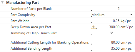
Based on these inputs, additional values are calculated and shown at the process in the Details view > Calculation
view scheme (combobox) under Manufacturing Valuation.
Step 4: Select and Describe Material
Based on the material classification, a selection list of compatible materials is available in the Details view > Calculation ![]() view scheme (combobox) under Manufacturing Valuation > Material Selection. The respective material will later be added to the structure.
view scheme (combobox) under Manufacturing Valuation > Material Selection. The respective material will later be added to the structure.
You can use the following material classification with the cost model:
- Basic Materials > Metal > Steel
- Basic Materials > Metal > Steel > Quality Steel Unalloyed
- Basic Material > Metal > Nonferrous Metal > Light Metal > Aluminum
- Basic Material > Metal > Nonferrous Metal > Light Metal > Titanium Alloy
- Basic Material > Metal > Nonferrous Metal > Heavy Metal > Copper
Select Material Classification and Material
-
Select the material classification for the process in the Details view > Calculation
view scheme (combobox): -
Select an available material in the Material Selection, e.g. "
| Name | Value |
|---|---|
| Material Classification* |
Basic Materials > Metal > Steel > Quality Steel Unalloyed |
| * FACTON recommends compatible materials based on the material classification. | |
By selecting the material, the following properties are determined and displayed for the material:
- Density
- Tensile Strength
The entered values for the sheet dimensions Sheet width, length, and thickness are going to be added to the used material later on in the bill of materials (BOM) structure.
Describe Material
-
In the Structure view, select the
process " -
Enter the following values in the Details view > Calculation
view scheme (combobox) under Manufacturing Valuation > Material: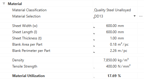
Technical parameters like Density and Tensile Strength are assumed from the material selection(master data).
Based on the entered and provided dimensions of the manufacturing part and the sheet, the Material Utilization will be calculated and added to the used material later on in the BOM structure.
Step 5: Check values for work steps "Deep Drawing", "Blanking", and "Bending"
The stamping process requires a wide range of individual work steps in order to manufacture a part.
To visualize complex deep drawing parts in detail, they must be broken down into separate work steps.
Depending on the Material Classification, each material is characterized by a Maximum Drawing Ratio. Exceeding this ratio can cause the sheet material to break. This is why several draws may be required for complex geometries/part sizes.
With FACTON the number of required work steps is calculated automatically at the stamping model (max. 5 draws). Each draw is characterized by a drawing and a retaining force.

The values for the work steps "Deep Drawing", "Blanking", and "Bending" are provided at the cost model based on previously defined values at the manufacturing part and material, yet they can be edited directly or overridden with F12 (see Step 9: Additional Fine Tuning).
Step 6: Select Machine and Times
Based on the calculated Relevant Press Force from the work steps, you can select the preferred machine in the Details view > Calculation ![]() view scheme (combobox) under Manufacturing Valuation > Machine.
view scheme (combobox) under Manufacturing Valuation > Machine.
Select Machine and Define Times
-
Select the machines for the process in the Details view > Calculation
view scheme (combobox):Machine Machine Selection Fully automatic horizontal multi-stage press | Stroke frequency: 60.00 - 100.00 1/min | press force: 8,000.00 kN
By selecting the machine, a value for the machine's stroke frequency and press force is provided.
-
Enter values for the primary and secondary processing times:
Primary Processing Time Additional Primary Processing Time 56 s / cycle
Secondary Processing Times Loading/Unloading/Transfer Time 85 s / cycle Greasing Time 12 s / cycle The primary and secondary processing times are now calculated based on the provided and entered values and sum up to the cycle time (= Primary Processing Time + Secondary Processing Time).
Step 7: Define Tools and Fixtures
In addition to the machine, you can also maintain values for
Define Details for
- Enter the following values in the Details view > Calculation view scheme (combobox) under Manufacturing Valuation > Fixtures:
Step 8: Complete Structure
Based on your entries, the BOM structure of the cost model is being automatically created via the "Complete Structure" function.
Complete structure of cost model
- In the Structure view select the process
- Right-click > Complete Structure.
- the selected material
- the selected machine
- a worker
- tools and fixtures
Alternative: F11 in the Structure view or Details view.
The structure is automatically generated based on your entries, and costs are being calculated.
Further changes are not applied immediately.
Perform the "Complete Structure" action again after every change to update your cost model.
All previously selected resources are inserted under the ![]() process
process
Calculated Values of the Cost Model
The following values are calculated using the data entered and then shown in the Details > Calculation view scheme:
- Cycle Time
- Cycles per Time
- Output per Cycle
- Output per Time
- Time per Unit Output
- Absolute Frequency of Occurrence
- Percentaged Frequency of Occurrence
Step 9: Additional Fine Tuning
Additionally, you can add or edit more details at the process in the Details > Calculation > Manufacturing Valuation (if required, override with F12):
| Group | Properties |
|---|---|
| Material |
|
|
Deep Drawing |
|
|
Blanking |
|
|
Bending |
|
|
(Manufacturing Valuation) |
|
| Machine |
|
Properties of the Stamping cost model (Calculation > Manufacturing Valuation)
Manufacturing Part group
The manufacturing part properties used to calculate the cost model are shown in this group.
Number of Parts per Blank
Enter the part number that is created per each sheet cut (the value "1" is set by default).
|
|
|
Part Complexity
Selection of the geometric complexity of the part in percent.
Has direct impact on the Complexity Coefficient (Deep Drawing) and the Relative Stroke Frequency of the machine.
|
|
|
Part Weight
Enter the weight of the finished part.
|
|
|
Deep Drawn Area per Part
The smallest or deepest deep drawn area at the part.
|
|
|
Trimming of Deep Drawn Part
Decision whether a trimming of the drawn part out of the sheet is required.
![]() Activating/deactivating directly possible via a checkbox.
Activating/deactivating directly possible via a checkbox.
Additional Cutting Length for Blanking Operations
Enter the additionally required cutting length for the blanking work steps.
![]() Direct input is possible.
Direct input is possible.
Additional Bending Length
Enter the additionally required length for the bending work steps.
![]() Direct input is possible.
Direct input is possible.
Material Group
The material properties used to calculate the cost model are shown in this group.
Material Classification
Selection of the material classification as basis for selecting the material. Usually the selection is made in the General Properties view schema and will then be assumed to the "Material" group in the Calculation view schema.
Under Details > General Properties:
|
|
|
Under Details > Calculation:
![]() Indirect input is possible using F12.
Indirect input is possible using F12.
Material Selection
Selection of the material.
|
|
|
Sheet Width (w)
Enter the sheet width for the sheet metal material.
|
|
|
Sheet Length (l)
Enter the sheet length for the sheet metal material.
|
|
|
Sheet Thickness (t)
Enter the sheet thickness for the sheet metal material.
|
|
|
Blank Area per Part
Enter the used area of the sheet metal blank per part. The value must be higher than the value of the Deep Drawn Area per Part.
![]() Direct input is possible.
Direct input is possible.
Blank Perimeter per Part
Enter the used perimeter of the sheet metal blank per part. The value must be higher than the value of the Perimeter of Deep Drawn Area per Part.
![]() Direct input is possible.
Direct input is possible.
Density
Density of the material.
![]() This value is required.
This value is required.
This value can be managed at the material (Details > Technical Data view scheme), or is applied when global templates are inserted.
Tensile Strength
Tensile strength of the material.
![]() This value is required.
This value is required.
This value can be managed at the material (Details > Technical Data view scheme), or is applied when global templates are inserted.
Material Utilization
Percentage value of the final material utilization.
Is calculated from:
- Number of Parts per Blank
- Part Weight
- Sheet Width (w)
- Sheet Length (l)
- Sheet Thickness (t)
Depends on: Material Classification
Deep Drawing group
In this group the properties of the work step "Deep Drawing" are displayed.
Complexity Coefficient
Percentage surcharge for the perimeter depending on the geometric complexity. The default values result from the selection of the Part Complexity:
| Part Complexity | Complexity Coefficient |
|---|---|
| Low | 0.00 % |
|
Medium |
50.00 % |
|
High |
100.00 % |
![]() Indirect input is possible using F12.
Indirect input is possible using F12.
Perimeter of Deep Drawn Area per Part
The perimeter of the smallest or deepest deep drawn area at the part.
![]() Direct input is possible.
Direct input is possible.
Intermediate Annealing
Decision whether an intermediate annealing process is required. The intermediate annealing allows a higher drawing ratio in the next drawing work step. The default setting is "no".
Has direct impact on the number of required draws and the maximum drawing ratio of subsequent draws.
![]() Activating/deactivating directly possible via a checkbox.
Activating/deactivating directly possible via a checkbox.
Drawing Clearance
Gap between the cavity and the drawing punch.
Is calculated from:
- Sheet Thickness (t)
Max. Drawing Ratio (First Draw)
The maximum drawing ratio in the first drawing work step (draw).
![]() Indirect input is possible using F12.
Indirect input is possible using F12.
Max. Drawing Ratio (Subsequent Draws)
The maximum drawing ratio from the second drawing work step (draw) on.
![]() Indirect input is possible using F12.
Indirect input is possible using F12.
First/Second/... Draw sub-groups
First/Second/... Draw
Sum of the required force of the individual drawing work step (draw). Up to 5 draws are possible.
Is calculated from:
- Drawing Force of the individual draw
- Retaining Force of the individual draw
Drawing Force
Enter the required drawing force for this drawing work step (draw).
Depends on:
- Material Classification
- Material Utilization
- Tensile Strength
![]() Indirect input is possible using F12.
Indirect input is possible using F12.
Retaining Force
Enter the required retaining force for this drawing work step (draw).
Depends on:
- Material Classification
- Material Utilization
- Tensile Strength
![]() Indirect input is possible using F12.
Indirect input is possible using F12.
Required Deep Drawing Force
Required press force for the "Deep Drawing" work step per stroke.
Is calculated from:
- First/Second/... Draw
![]() Indirect input is possible using F12.
Indirect input is possible using F12.
Blanking group
In this group the properties of the work step "Blanking" are displayed.
Press Force for Blanking Operations
Enter the additional press force for blanking work steps.
![]() Indirect input is possible using F12.
Indirect input is possible using F12.
Depends on: Material Classification
Press Force for Trimming of Deep Drawn Part
Enter the additional press force for trimming the drawn part.
![]() Indirect input is possible using F12.
Indirect input is possible using F12.
Depends on: Material Classification
Required Blanking Force
Required press force for the "Blanking" work step per stroke.
Is calculated from:
- Press Force for Blanking Operations
- Press Force for Trimming of Deep Drawn Part
Bending group
In this group the properties of the work step "Bending" are displayed. The group is only available if a value for Additional Bending Length (higher than "0") was defined before in group "Manufacturing Part".
Total Bending Length
Enter the total length of all bending edges.
Is calculated from:
- Number of Parts per Blank
- Additional Bending Length
![]() Indirect input is possible using F12.
Indirect input is possible using F12.
Required Bending Force
Required press force for the "Bending" work step per stroke.
Is calculated from:
- Total Bending Length
Depends on:
- Material Classification
- Sheet Thickness (t)
- Tensile Strength
Required Press Force
Displays the theoretical press force for producing the part, without surcharges.
Is calculated from:
- Required Deep Drawing Force
- Required Blanking Force
- Required Bending Force
% Additional Press Force
Enter the percentage surcharge on the required press force.
![]() Direct input is possible.
Direct input is possible.
Additional Press Force
Displays the absolute surcharge on the required press force per stroke.
Relevant Press Force
Displays the relevant press force for producing the part, with surcharges.
Is calculated from:
- Required Press Force
- Additional Press Force
Machine Group
The machine properties used to calculate the cost model are shown in this group.
Machine Selection
Select a machine. A suitable selection list of machines is offered based on the calculated relevant pressing force.
|
|
|
Stroke Frequency of the Machine
Maximum stroke frequency of the machine that is available.
![]() This value is required.
This value is required.
This value is required and can be managed at the machine (Details > Technical Data view scheme), or is applied when global templates are inserted.
Press Force of the Machine
Displays the maximum press force of the machine.
![]() This value is required.
This value is required.
This value is required and can be managed at the machine (Details > Technical Data view scheme), or is applied when global templates are inserted.
Relative Stroke Frequency
Share of the stroke frequency that is actually used. The default values result from the selection of the Part Complexity:
| Part Complexity | Relative Stroke Frequency |
|---|---|
| Low | 100.00 % |
|
Medium |
75.00 % |
|
High |
50.00 % |
![]() Direct input is possible.
Direct input is possible.
Relevant Stroke Frequency
Stroke frequency that is actually used.
Is calculated from:
- Stroke Frequency of the Machine
- Relative Stroke Frequency
Primary Processing Time group
The primary processing times used to calculate the cost model are shown in this group.
Primary Processing Time
Time in which the actual activity of a process is performed.
Is calculated from:
- Press Time
- Additional Primary Processing Time
Press Time
Entire time to press all strokes.
Is calculated from:
- Relevant Stroke Frequency
Additional Primary Processing Times
Possibility to add primary processing times that have not been considered.
![]() Direct input is possible.
Direct input is possible.
Secondary Processing Time group
The secondary processing times used to calculate the cost model are shown in this group.
Secondary Processing Time
Necessary idle time of a process in which its actual activity cannot be performed.
Is calculated from:
-
Loading/Unloading/Transfer Time
- Greasing Time
Loading/Unloading/Transfer Time
Total time for loading and unloading the machine with a workpiece, as well as for the transfer.
![]() Direct input is possible.
Direct input is possible.
Greasing Time
Time for greasing the tool.
![]() Direct input is possible.
Direct input is possible.
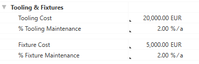
Tooling & Fixtures group
In this group you can define the costs for tools and fixtures, as well as their annual maintenance costs.
Tooling Cost
Costs required for used tools.
![]() Direct input is possible.
Direct input is possible.
% Tooling Maintenance
Share of maintenance costs for tools per year.
![]() Direct input is possible.
Direct input is possible.
Fixture Cost
Costs required for used fixtures.
![]() Direct input is possible.
Direct input is possible.
% Fixture Maintenance
Share of maintenance costs for fixtures per year.
![]() Direct input is possible.
Direct input is possible.