Calculate Injection Molding
You can use the Calculate Injection Molding cost model to calculate the process times and costs for the injection molding manufacturing process in plastics processing. In FACTON, there are value rule tables and formulas defined at the cost model providing you with information on:
- the anticipated cycle time,
- the possible process output per time and cycle,
- the material consumption,
- the clamping force and the shot volume of the machine, and
- the primary and secondary processing times.
The table shows typical application scenarios of the cost model for parts and industry:
| Typical Parts | Typical Industries |
|---|---|
|
|
You need knowledge of the
Sequence
The following example illustrates the process and structure of the
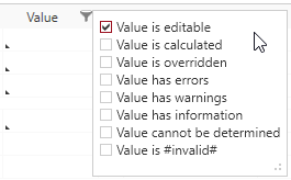
The black triangle ◣ helps you identify editable values.
The Consistency Rule Violation check is available to you when entering values. The consistency rule violations check notifies when there are missing values and verifies the accuracy of the values entered.
When you hover over one of the Consistency rule violations icons with your mouse, a tooltip appears with the specific reason for the consistency rule violations.
Step 1: Create Should Cost Calculation
Further Information > Create Should Cost Calculation
Step 2: Insert Part
- Select the
 should cost calculation in the Structure view.
 -
In the ribbon, click on Edit > Insert >
 Part (Piece).
A part is inserted into the calculation structure.
- Define the following properties in the Details view (General Properties
 view schema):
| Material Classification* | Basic Material > Plastic Material > Thermoplast > ABS - Acrylnitril-Buthadiene-Styrene |
| Manufacturing Method* | Primary Shaping > Casting > Injection Molding |
| *FACTON recommends the matching materials and machines according to your choices in the material classification and manufacturing method. | |
You can use the following
For Thermoplast (Basic Materials > Plastic Material > Thermoplast):
- PE - Polyethylene > PE-HD - Polyethylene high density
- PE - Polyethylene > PE-HD - Polyethylene low density
- PP - Polypropylene
- PA - Polyamide > PA 6 - Polyamide 6
- PA - Polyamide > PA 66 - Polyamide 66
- PA - Polyamide > PA 11 - Polyamide 11
- PA - Polyamide > PA 12 - Polyamide 12
- PS - Polystyrene
- ABS - Acrylnitrile-Buthadiene-Styrene
- SAN - Styrene-Acrylnitrile
- ASA - Acrylonitrile Styrene Acrylate
- PC - Polycarbonate
- PC / ABS - Polycarbonate/Acrylnitrile Buthadiene Styrene
- PVC - Polyvinylchloride > PVC-U - Polyvinylchloride Unplasticized (hard)
- PVC - Polyvinylchloride > PVC-P - Polyvinylchloride Plasticized (soft)
- PMMA - Polymethyl methacrylate
- PET - Polyethylene terephthalate
- PBT - Polybutylene terephthalate
- POM - Polyoxymethylene
- PPE/PA - Polyphenylene ether/Polyamide
- PSU - Polysulfone
- PES - Polyethersulfone
- CA - Cellulose acetate
- CP - Cellulose proprionate
- CAP - Cellulose acetopropionate
- CAB - Cellulose acetobutyrate
- PTFE - Polytetrafluoroethylene
- ETFE - Ethylene tetrafluorethylene
- FEP - Tetrafluorethylene/Hexafluorpropylene
- PCTFE - Polychlortrifluorethylene
For Elastomers (Basic Materials > Plastic Material > Elastomer):
- EVA - Ethylene Vinyl Acetate
Step 3: Insert Process
- Select the part in the Structure view.
-
In the ribbon, click on Edit > Insert >
 Process.
A process is inserted in the calculation structure.
-
In the Details view (Calculation view schema
 ), select the manufacturing valuation Calculate Thermoplastic Injection Molding.
The process is automatically renamed to "Injection Molding".
A new group Manufacturing Valuation appears with sub-groups.
-
In the Details view, click on the filter symbol and activate the checkbox for the values to be entered.
-
For example, enter the following values:
Input parameters Runner Type Hot Runner Cavity Count selected 2.00 pc/cycle Component 1 Material Classification is automatically assumed from the
partMaterial Selection ABS - Granules
After selecting, the density and other material parameters are shown.
Part (Component) Weight 0.1 kg/pc Projected Area of Part 50 cm²/pc Maximum Wall Thickness 3 mm Machine Selection A matching machine is being determined based on the calculated values for clamping force and shot volume.
You can also choose a different machine from the combobox.
Labor Group EG05
The corresponding labor costs for the worker are determined based on the sector, the reference location, the reference date, and the labor group.
Number of Workers 2 -
Enter some more values for other process parameters, tools and fixtures.
Other Process Parameters Slider Type Mechanical Slider Insertion Parts Necessary 
Part Removal Type Robot Unload
A further property for selecting the robot unloading type.
Unload Robot Unload Robot Industrial robot | Payload: 6.00 kg | Reach: < 1,820.00 mm Tools and Fixtures Tool Cost 25,000.00 EUR % Tool Maintenance 2 %/a Fixture Cost 2,500.00 EUR % Fixture Maintenance 2 %/a
Based on the selected material classification you can choose a material in the material selection. Accordingly, the following property values are determined via value rules:
- Density
- Available Clamping Force
- Melt Temperature
- Tool Temperature
- Demolding Temperature
- Defusion Rate
The properties are shown at the process in the Details view (Calculation view schema ![]() ) under Manufacturing Valuation > Miscellaneous Parameters > Component 1 > Material.
) under Manufacturing Valuation > Miscellaneous Parameters > Component 1 > Material.
Step 4: Complete Structure
Based on your entries, the BOM structure of the cost model is being automatically created via the "Complete Structure" function.
Complete Structure of the Cost Model
- Select the process in the Structure view.
- Right-click > Complete Structure.
Alternative: F11 in the Structure view or Details view.
Based in your selection, a structure is automatically completed.
Further changes are not applied immediately.
Perform the "Complete Structure" action again to update your cost model.
Properties of the Injection Molding cost model (Calculation > Manufacturing Valuation)
Component 1 group (under > Input Parameters)
Material Classification
The material classification of the process.
Material Selection
Select the material according to the selected material classification of the process. Defines the density.
![]() This value is required.
This value is required.
This value can be managed at the material (Details > Technical Data view schema), or is applied when global templates are inserted.
Density
Density of the material.
![]() This value is required.
This value is required.
This value can be managed at the material (Details > Technical Data view schema), or is applied when global templates are inserted.
Cavity Count
Runner Type
Gating System Volume
Volume of the gating system. The property is only visible, if a value for "Runner Type" has been set.
|
|
|
Part Weight
Weight of the part.
Projected Area of Part
The area of the part projected in the mold parting surface.
|
|
|
Max. Wall Thickness
Maximum wall thickness of the part.
|
|
|
Material group (under > Other Parameters > Component 1)
The material properties used to calculate the cost model are shown in this group.
Available Clamping Force
Clamping force per area for a given material.
Depends on: Material Classification
![]() Indirect input is possible using F12.
Indirect input is possible using F12.
Melt Temperature
Temperature the melted material has during injection.
Depends on: Material Classification
![]() Indirect input is possible using F12.
Indirect input is possible using F12.
Tool Temperature
Temperature of the tool which causes cooling of the melted material.
Depends on: Material Classification
![]() Indirect input is possible using F12.
Indirect input is possible using F12.
Demolding Temperature
Target temperature when cooling is finished and demolding can be done.
Depends on: Material Classification
![]() Indirect input is possible using F12.
Indirect input is possible using F12.
Defusion Rate
Factor that specifies how much area of a given material can cool down per time.
Depends on: Material Classification
![]() Indirect input is possible using F12.
Indirect input is possible using F12.
Part group (under > Other Parameters > Component 1)
The part properties used to calculate the cost model are shown in this group.
Part Volume
Volume of the part. Is calculated when entering a value for the "Part Weight".
![]() Indirect input is possible using F12.
Indirect input is possible using F12.
Projected Area of Gating System
The area of the gating system projected in the mold parting surface. Is calculated when entering a value for the "Projected Area" of the part.
Is calculated from:
- Ratio of area to volume (cm²/cm³)
- Gating System Volume
![]() Indirect input is possible using F12.
Indirect input is possible using F12.
Material Usage
Required material weight including gating system weight. Is calculated if a value for "Material Selection" has been set in the Component 1 group (under > Input Parameters).
Is calculated from:
- Density
- Material Usage Volume
Sprue Weight
Sprue Recycling Rate
Recyclable Material
Material mass of the gating system which can be recycled. Is calculated if a value for "Material Selection" has been set in the Component 1 group (under > Input Parameters).
Is calculated from:
- Density
- Gating System Volume
Clamping Force group (under > Calculated Parameters)
The clamping force properties used to calculate the cost model are shown in this group.
Clamping Force by Projected Area of Part
Clamping force by projected area of part in the mold parting surface.
Is calculated from:
- Specific Clamping Force
- Projected Area of Part
% Additional Clamping Force for Safety
Percentaged additional clamping force for safety ratio by projected area. Is calculated when entering a value for the "Additional Clamping Force for Safety".
![]() Direct input is possible.
Direct input is possible.
Additional Clamping Force for Safety
Absolute additional clamping force for safety ratio by projected area. Is calculated when entering a value for the "% Additional Clamping Force for Safety".
![]() Direct input is possible.
Direct input is possible.
% Additional Clamping Force for Sliders
Percentaged additional clamping force for sliders by projected area. Is calculated when entering a value for the "Additional Clamping Force for Sliders".
![]() Direct input is possible.
Direct input is possible.
Additional Clamping Force for Sliders Ratio
Absolute additional clamping force for sliders by projected area. Is calculated when entering a value for the "% Additional Clamping Force for Sliders".
![]() Direct input is possible.
Direct input is possible.
Required Clamping Force for Part
Required clamping force for the part with additional clamping forces.
Is calculated from:
- Clamping Force by Projected Area of Part
- Additional Clamping Force for Safety
- Additional Clamping Force for Sliders Ratio
Clamping Force by Projected Area of Gating System
Clamping force by projected area of the gating system in the mold parting surface.
Is calculated from:
- Available Clamping Force
- Projected Area of Gating System
Relevant Clamping Force
Required total clamping force for all cavities and the gating system.
Is calculated from:
- Cavity Count (under > Input Parameters > Component 1)
- Required Clamping Force for Part
- Clamping Force by Projected Area of Gating System
Machine group (under > Calculated Parameters)
The machine properties used to calculate the cost model are shown in this group.
Available Clamping Force
Maximum clamping force of the machine that is available.
![]() This value is required.
This value is required.
This value is required and can be managed at the machine (Details > Technical Data view schema), or is applied when global templates are inserted.
Shot Volume of the Machine
Maximum shot volume of the machine that is available.
![]() This value is required.
This value is required.
This value is required and can be managed at the machine (Details > Technical Data view schema), or is applied when global templates are inserted.
Possible Cavity Count by Clamping Force
The possible count of cavities determined with respect to the available clamping force.
Is calculated from:
- Available Clamping Force
- Clamping Force by Projected Area of Gating System
- Required Clamping Force for Part
Possible Cavity Count by Shot Volume
The possible count of cavities determined with respect to the available shot volume.
Is calculated from:
- Shot Volume of the Machine
- Gating System Volume
- Part Volume
Cavity Count Suggested
Number of cavities.
Is calculated from:
- Possible Cavity Count by Clamping Force
- Possible Cavity Count by Shot Volume
![]() Indirect input is possible using F12.
Indirect input is possible using F12.
Primary Processing Times group (under > Calculated Parameters)
The primary processing times used to calculate the cost model are shown in this group.
Injection and Cooling Time
Time for injecting and cooling down the part for removal and further usage. Is calculated from:
- Injection Time (under Other Parameters > Component 1 > Processing Time)
- Cooling Time (under Other Parameters > Component 1 > Processing Time)
- Max. Wall Thickness
- Melt Temperature
- Tool Temperature
- Demolding Temperature
- Defusion Rate
Tool Opening and Closing Time
Time for opening and closing the tool. Depends on: Machine Size (Available Clamping Force)
![]() Direct input is possible.
Direct input is possible.
Additional Time for Multi-Component Process
Time required for a multicomponent injection molding process (i.e. a second component can be specified in the injection molding process). Is calculated if the ![]() "Is Multi Component Process" checkbox (under > Input Parameters) has been activated.
"Is Multi Component Process" checkbox (under > Input Parameters) has been activated.
![]() Indirect input is possible using F12.
Indirect input is possible using F12.
Additional Primary Processing Times
Possibility to add primary processing times that have not been considered.
![]() Direct input is possible.
Direct input is possible.
Primary Processing Time
Time in which the actual activity of a process is performed.
- Injection and Cooling Time
- Tool Opening and Closing Time
- Additional Time for Multi-Component Process
- Additional Primary Processing Times
Secondary Processing Times group (under > Calculated Parameters)
The secondary processing times used to calculate the cost model are shown in this group.
"Insertion Parts Necessary" checkbox
Selection whether insertion parts are necessary or not.
Parts Insertion Time
Time for inserting the parts into the machine. Is calculated when the selection for necessary insertion parts is activated.
![]() Indirect input is possible using F12.
Indirect input is possible using F12.
Slider Type
Slider Cycle Tim
Part Removal Type
Two Plate Ejector
Additional Secondary Processing Times
Possibility to add secondary processing times that have not been considered.
![]() Direct input is possible.
Direct input is possible.
Secondary Processing Time
Necessary idle time of a process in which its actual activity cannot be performed.
Is calculated from:
- Parts Insertion Time
- Additional Secondary Processing Times