Cost Model - Chipping
You can use the Chipping cost model for calculating the process times and costs for the chipping manufacturing process in metal working. In FACTON, there are value rule tables, and at the cost model formulas are defined that provide you with information on:
- The anticipated cycle time,
- the possible process output per time and cycle,
- the material consumption
- the cutting speed and feed per tooth, and
- primary and secondary processing times.
The table shows typical application scenarios of the cost model for parts and tools:
| Typical parts | Typical tools |
|---|---|
|
|
You need knowledge of the
Procedure
The following example illustrates the process and structure of the
The black triangle helps you identify values that you can enter ![]() .
.
The Consistency Rule Violation check is available to you when entering values. The consistency rule violations check notifies you of missing values and verifies the accuracy of the values entered.
When you hover over one of the Consistency rule violations icons with your mouse, a tooltip appears with the specific reason for the consistency rule violations.
Step 1: Create Should Cost Calculation
Create
- You are logged in as Calculator.
- You are in the Calculations workspace.
- In the ribbon, click on Manage.
- Select the
 Should Cost Calculation
The created calculation opens in a new tab.
You are the owner of the calculation that was created.
- Define the following properties for the Should Cost Calculation in the Details view:
- Material Overhead Rate
- Manufacturing Overhead Rate
- Administrative Overhead Rate
- Sales Overhead Rate
- Development Overhead Rate
- Logistics Overhead Rate
| Reference Company* | |
| Industrial Sector |
|
| Production Location | World » Europe » Germany |
| Reference Company Plant Revenue | 100m EUR |
| Reference Company Material Share | 50% |
| Reference Company Degree of Automation | Medium |
| Production Planning | |
| Production Quantity | 100,000 pc / a |
| Target Profit Rates | |
| Target Profit Rate on Raw Material | 2 % |
| Target Profit Rate on Purchased Material | 2 % |
| Target Profit Rate on Manufacturing | 2 % |
|
* Values are determined for the following properties using value rules based on your inputs under reference companies: |
|
Step 2: Insert Process
Insert Process
- In the Structure view, select the calculation element you wish to insert under the process.
- Click Edit ► Insert ►
 Process in the ribbon.
A process is inserted in the calculation structure.
- Change the label to
- Define the following properties for the process in the Details view:
- In the Details ► General ► Valuation view, select the valuation Cost Model:
A new Cost Model group appears with subgroups.
| Technical Descriptions | |
| Material Classification* |
|
| Manufacturing Method* |
|
| * FACTON recommends the appropriate materials and machines in the queries for the processes by allowing you to select the material classification and manufacturing process. | |
When changing valuations the sub-elements are grayed-out and no longer considered in the calculation.
Step 3: Insert Material
To use FACTON content for tool data, the Material Classification must be entered at the material.
Values are determined for the following work step properties using value rules via the Selection of the Material Classification that is assigned to a chipping material group and the Selection of the Chipping Tool:
- Cutting Speed
- Number of Teeth
- Feed per Tooth
You can view the »Chipping Material Group« property under Details ► General ► Cost Model ► Material.
You can insert
The latter is shown in the following, because it illustrates the inputs required for calculation.
Insert Local Material
- Select the »Chipping« process in the Structure view.
- Click on Edit ► Insert ►
 Insert New Local Material (Mass).
A local material is inserted under the »Chipping« process.
- Change the label to »Chipping Material«.
- Under Details ► Technical Description ► Material Classification, select a material classification.Note
You can use the following
- Basic Steel
- Quality Steel Unalloyed & Alloyed
- Stainless Steel Unalloyed
- Tool Steel
- Steel with Special Physical Properties
- Alloyed Steel / Construction Steel / Chemical Resistant Steel
- Special Purpose Steel
- Cast Iron
- Nonferrous Metal
- Titanium Alloy
- Plastic Material
The Material Classification Properties group appears under Technical Description.
- Define the following properties for the
General Price per Unit  1.75 EUR / kg
The following property is shown at the process in the Cost Model ► Material group based on the material classification
- Chipping Material Group
Step 4: Insert Work Steps
A range of separate work steps is required in order to manufacture a component in the chipping process. To visualize complex chipping parts in detail, they must be broken down into separate work steps.
FACTON lets you define multiple work steps at the Chipping cost model. You can assign the work steps to the machining units via a selection list.
Insert Work Steps
- Select the »Chipping« process in the Structure view.
- In the Details view, expand the group Cost Model ► Work Steps.
- Click on the
 button next to the Value column in the Work Steps row.
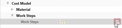
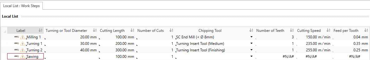
The Local List: Work Steps tab opens.
For more information on the work steps, see: Work Step Properties
- Right-click in the empty area of the tab ►
 New.
New.A new row is added to define your work step.
- Create two additional rows for the work step.
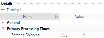
- In the Local List: Work Step tab, enter a value for Rotating Chipping for the following properties of the work step:
Label Turning or Tool Diameter Cutting Length Chipping Tool Milling 1 20 mm 100 mm Milling » Solid carbide end mill (< 8 mm) Turning 1 30 mm 200 mm Turning » Indexable Insert Turning Tool (Avg. Machining) Turning 2 40 mm 300 mm Turning » Indexable Insert Turning Tool (Finishing) NoteRotating Chipping is selected by default. You can see it, when the checkbox is activated under the Local List: Work Steps tab ► View Details.
These values are required in order to calculate additional values.
- Cutting Speed
- Number of Teeth
- Feed per Tooth
- Right-click in the empty area of the tab ► New.
A new row is added for you to define your work step.
- In the Details view, enter a value for Non-rotating Chipping for the following properties of the work step:
General Name »Sawing« Primary Processing Times Rotating Chipping Checkbox: »No« Cutting Length »100 mm« Non-rotating ► Feed Speed »400 mm / min« These values are required in order to calculate additional values.
- Close the Local List: Work Steps tab.
The tab is shown with your calculation and the Chipping cost model.
Values are determined for the following work step properties using value rules via the Selection of the Material Classification, which is assigned to a chipping material group and the Selection of the Chipping Tool:
You can see these properties in the Local List: Work Steps tab and in the Details ► Primary Processing Times ► Rotating view.
| Rotating Chipping | Non-rotating Chipping |
|---|---|
Enter the following in the Local List tab:
|
Enter the following via the Details view:
|
|
Entering this information calculates the following values: |
|
|
|
General group
This group shows the general work step properties.
| Properties | Description | Input Possible |
Calculated |
Required |
|---|---|---|---|---|
| Label | Work Step Label | direct | x | |
| Material Classification | Shows the material classification that was defined at the material | |||
| Chipping Material Group | Shows the chipping material group that was determined by selecting the material classification via value rules | with F12 | ||
| Chipping Tool | Selection of the tool for determining the cutting data | direct | x | |
| Assigned Machining Unit | The assigned machining unit for this work step |
Primary Processing Times
This group shows the primary processing times for the work step.
| Properties | Description | Input Possible |
Calculated |
Required |
|---|---|---|---|---|
| Rotating Chipping | Specifies, whether the part is rotary machined or not | direct | x | |
| Cutting Length | Length of the cutting edge or contour of the workpiece that is machined in the work step | direct | x | |
| Number of Cuts | Number of repetitions necessary for achieving the desired cutting depth | direct | ||
| Primary Processing Time |
Time in which the actual activity of a process is performed
|
x |
Primary Processing Times ► Rotating Subgroup
This group shows the primary processing times for the work step.
| Properties | Description | Input Possible |
Calculated |
Required |
|---|---|---|---|---|
| Turning or Tool Diameter | Turning: Diameter of the cutting part level Milling/Drilling: Diameter of the tool |
direct | x | |
| Number of Teeth | The count of teeth of the tool Note: For turning or drilling, the count is always 1. |
with F12 | x | |
| Cutting Speed | The operating speed of the tool | with F12 | x | |
| Feed per Tooth | Specifies, how deep a tool edge can move into a material | with F12 | x | |
| Rotational Speed | Turning: Rotational speed of part Milling/Drilling: Rotational speed of tool | with F12 | ||
| Feed Speed |
The speed of the tool during rotating chipping
|
x |
Primary Processing Times ► Non-rotating Subgroup
This group shows the primary processing times for the work step.
| Properties | Description | Input Possible |
Calculated |
Required |
|---|---|---|---|---|
| Feed Speed | The speed of the tool during non-rotating chipping is not calculated. direct input required for non-rotating chipping |
direct | x |
Secondary Processing Times Group
This group shows the secondary processing times for the work step.
| Properties | Description | Input Possible |
Calculated |
Required |
|---|---|---|---|---|
| Loading |
Selection whether time is required for loading or not | direct | ||
| Loading Time |
Time for loading the machine with a part
|
with F12 | x | |
| Unloading | Selection, whether time is required for unloading or not | direct | ||
| Unloading Time |
Shows the time for unloading the part
|
with F12 | x | |
| Change tool | Selection, whether time is required for changing the tool or not | direct | ||
| Chip to Chip Time |
Shows the time to change a tool, including positioning at a similar point on the part
|
x | ||
| Reclamping Part | Selection, whether time is required for reclamping the tool or not | direct | ||
| Reclamping Time |
Shows the time for changing the clamping base of a part
|
with F12 | x | |
| Positioning Tool | Selection, whether time is required for positioning the tool or not | direct | ||
| Positioning Time |
Shows the time for the additional positioning of a tool
|
with F12 | x | |
| Positioning Count | Specifies, how often the part is positioned | direct | ||
| Secondary Processing Time | Waiting periods due to expiration of a process in which the actual activity cannot be performed. | x |
Process Time Group
This group shows the processing time for the work step. The processing time is derived from the sum of the primary and secondary processing times.
Technical Description Group
The technical descriptions of the work step, such as label and description, are shown and managed in this group.
Step 5: Insert Machine
You can use the Rotating Speed from the work steps to determine the required machine and insert it.
To calculate the cutting force and speed the Machine Type, Machining Units Count, Parallel Processing and Rotating Speed must be entered at the machine:
You can insert
The latter is shown in the following, because it illustrates the inputs required for calculation.
Insert Local Machine
- Select the »Chipping« process in the Structure view.
- Click on Edit ► Insert ►
 Insert New Local Machine in the ribbon.
A machine is inserted under chip removal »Chipping« process.
- Change the label to »Chipping Machine«
- Under Details ► Technical Description ► Machine Type, select a machine type for the »Chipping Machine«.Note
You can use the following
- Band Saw Machine
- Machining Center
- Hacksaw Machine
- Multi-Spindle Automatic Machine
- Rotary Transfer Machine
- Automatic Bar Turning Machine
- Universal Turning Center
- Universal Milling Center
- Gear Milling Machine
The Machine Type Properties group appears under Technical Description.
- In the Details ► Technical Description view, enter a value for the following properties:
- Machining Units Count
- Parallel Processing
- Rotational Speed
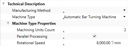
This entry is used for calculating the relevant stroke frequency.
- Define the following properties for the
Acquisition Costs Acquisition Value 100,000 EURFixed Machine Costs Depreciation Period 6 a
Step 6: Insert Machining Units
You can insert a certain number of machining units depending on the machine in use.
A machining unit is that area of the machine, in which the material is clamped and machined. Depending on the machine, multiple machining units can be managed by making parallel processing possible.
Insert Machining Units
- Select the »Chipping Machine« in the Structure view.
- Click on Edit ► Insert ►
 Machining Unit in the ribbon.
A machining unit is inserted under the machine.
- Change the label to »Machining Unit 1«.
- Repeat steps 1 through 2.
- Change the label to »Machining Unit 2«.
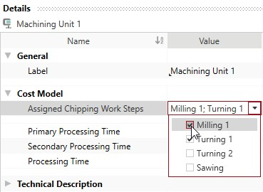
Step 7: Assign Work Steps
The next step is to assign work steps to the machining units. Assigning this information calculates the following properties:
| Property | Description |
|---|---|
| Primary Processing Time | Time in which the actual activity of a process is performed |
| Secondary Processing Time | waiting periods due to expiration of a process in which the actual activity of a process are not performed |
| Processing Time | Time derived from the sum of the primary and secondary processing times |
Assign Work Steps
- Select the »Machining Unit 1« in the Structure view.
- In the Details ► Cost Model ► view, click on
 .
.The selection list with the work steps opens.
- Activate the checkbox in front of the work steps that you wish to assign to »Machining Unit 1«:
- »Milling 1«
- »Turning 1«
- Select the »Machining Unit 2« in the Structure view.
- In the Details ► Cost Model ► Select Work Steps view, click .
The selection list with the work steps opens.
- Activate the checkbox in front of the work steps that you wish to assign to »Machining Unit 2«:
- »Turning 2«
- »Sawing«
Calculated values of the Chipping cost model:
The following values are calculated using the data entered and then shown in the Details ► General ► Cost Model view:
- Cycle Time
- Ʃ Measure Values Cycle Time
- Cycles per Time
- Output per Cycle
- Output per Time
- Time per Unit Output
- Manufacturing Scrap Rate
- Production Cost
Step 8: Insert Worker and Tool
Insert Worker
- In the Structure view, select the
- In the ribbon, click on Edit ► Insert ►
 Worker.
The corresponding labor costs for the worker are determined based on the sector, the reference location, the reference date and the labor group.
Insert Tool
- In the Structure view, select the process
- Click Edit ► Insert ►
 Insert New Local Tool.
The tool is inserted under the process.
Step 9: Additional Fine Tuning
You can continue fine tuning the settings in the Details ► General ► Cost Model view:
| Group | Properties |
|---|---|
| Work Steps |
|
| Secondary Processing Times |
|
| Processing Times |
|
Properties of the Cost Model - Chipping
Material Group
This group shows the chipping material group of the material that is used for chipping. The substance classification for chipping is based on the ISO 513 standard.
Work Steps Group
The work step properties in the chipping process that are used for calculating the cost model are shown in this group. The ![]() button opens the Local List: Work Steps tab, where you can manage the work steps.
button opens the Local List: Work Steps tab, where you can manage the work steps.
Machine
The machine properties used to calculate the cost model are shown in this group.
| Machine Properties | Description | Input Possible |
Calculated |
Required |
|---|---|---|---|---|
| Machine Type | Assignment of a machine to a specific group with the corresponding properties This value is required in order to manage additional machine type properties. It can be managed at the machine (Details view ► Technical Description), or is applied when global templates are inserted. |
x | ||
| Machining Units Count | Shows the count of available machining units on the machine | |||
| Parallel Processing | Selection whether the machining units can be used simultaneously | |||
| Rotational Speed | Turning: Rotational speed of part Milling/Drilling: Rotational speed of tool This value is required in order to manage additional machine type properties. It can be managed at the machine (Details view ► Technical Description) or is applied when master data is inserted. |
x |
Secondary Processing Times
The secondary processing times used to calculate the cost model are shown in this group.
| Secondary Processing Times | Description | Input Possible |
Calculated |
Required |
|---|---|---|---|---|
| Loading Time |
Time for loading the machine with a part
|
with F12 | ||
| Unloading Time |
Time for unloading the part
|
with F12 | ||
| Chip to Chip Time |
Time to change a tool, including positioning at a similar point on the part
|
with F12 | ||
| Reclamping Time |
Time for changing the clamping base of a part
|
with F12 | ||
| Positioning Time |
Time for the additional positioning of a tool.
|
with F12 | ||
| Indexing Time |
Necessary time of the machine to hand over the part to the next machining unit
|
with F12 |
Primary Processing Times
The primary processing times used to calculate the cost model are shown in this group.
| Processing Times | Description | Input Possible |
Calculated |
Required |
|---|---|---|---|---|
| Processing Time |
Sum of the primary and secondary processing times
|
x | ||
| % Additional Processing Time | Percentaged additional processing times not considered yet is calculated, when entering a value for the additional processing time |
direct | ||
| Additional Processing Time | Absolute additional processing times not considered yet is calculated, when entering a value for the % additional processing time |
direct |